• Please review our updated Terms and Rules here

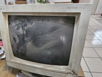
Old monitor Acerview 11vga

Datamisc

Member
Joined
Feb 3, 2024
Messages
31
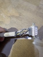
So I finally got to rescue my old computer from my father's claws, it was an acer 1116SX, that turns on but won't boot because the CMOS clock died (replacement is being sent from e-bay) and my headache, the monitor, it seems that it had been "serviced" before on the connector, which I checked for continuity, and it seems to be "ok".
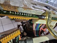
After checking the outside, I saw some sort of brownish ooze that went inside, so before turning it on, I opened the monitor and saw how it creeped on the PBC that is on the CRT, I cleaned that stuff with isopropyl alcohol to the best of my knowledge.
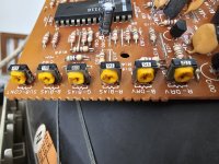
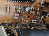
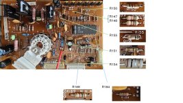
As you can see in the pictures there was some corrosion on some of the resistors (but when checked they do give the proper resistance), and at least 3 of the variable resistors? (not sure if those are that) seem with a lot of corrosion.
I decided to turn the monitor on, and to my surprise I could hear the high voltage pitch and felt the static from the screen, but no image. When I turn off the monitor, I can see how the scan disappears like the old days, up to a vertical line at the center, then a dot and then shuts down.
I do not want to do anything before I get a plan on what to check or what to change. any help would be appreciated.
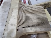
20240107_123749.jpg20240107_123812.jpg

The "repaired connection"
20240118_134554.jpg

The brown stuff that got inside the monitor.
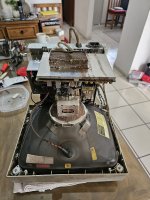
20240117_122822.jpg20240118_134356.jpg

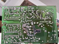
After some cleaning with isopropyl alcohol, the back was checked, all the traces seem to be ok.
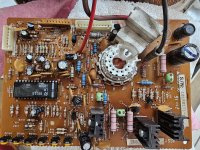
20240122_140454.jpg20240122_140440.jpg

The corroded variable resistors? not sure if those are that.
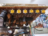
20240125_085858.jpg20240125_092652.jpg20240125_092658.jpg

Thank you for reading this!
 
Can anyone give me some advice on how to verify what is wrong or what should I check or change first? I've read that the capacitors are not always the problem. Thank you!
 
Your VDU may well be working fine.

Whatever you do initially, don't start working on it and randomly changing caps or any other components, unless there is a definite reason to do it.

If these VDU's are not receiving a proper set of video signals and or sync pulses, the CRT's beam will be blanked out and the VDU will behave exactly as it is doing. Sometimes, even increasing the brightness control won't bring up the raster scan with incorrect or missing signals. Its behavior is normal if it is not plugged onto a working video card in a working computer and all the signal connections are correct.

The first thing to do is to give it a basic clean. Don't remove the EHT (anode cap) leave that connected and you won't have to worry about discharging the CRT. You can unplug the neck board, the charge in the CRT cannot come out the CRT's base pins.

See if you can find the schematic, post it if you can. You need to check the input connector and the signals feeding the VDU with a scope, to find out if the correct signals are there, or not.
 
Thank you, Hugo, I will confess I was about to change the caps (I even made an excel with all the caps on that board) or the variable resistors, but after reading some post I came to one of yours that said exactly that, to not mess with caps unless there is a reason, that is the advice that made me post here.
I already ordered a scope and will do what you suggested.

Regarding the schematic, despite several days trying different search engines, even using ChatGPT searching for the model (which by the way is 7031) and there seems to be none online, so will work a bit blind. I am comfortable with electronics and in no way an expert in CRT monitors, but I learn fast and I'm sure with some guidance will get this monitor working.
At least the connector and its pin assignments should match other similar VDU's, see what you can find there.
 
After doing a lot of research, there is no schematics for it, I even found it was made by Continental Systems Inc, with model 7031, but nothing else.
I have located the connector and pin assignments, will work there and post here the results. Thank you, Hugo.
 
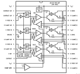
Found the schematic for the Video Amplifier chip inside the monitor, would that help us to make a correct diagnosis while I get my oscilloscope? thank you again for your help Hugo.
 

Attachments

  • LM1203.PDF
    566.5 KB · Views: 3
The video connector looks fine, and might even be original. It's just missing the cover shell, which were often made from metal and held on with screws. You can still buy replacements. As others have said, don't do anything until you test it with a signal source.
 
Ok, so after a lot of days watching videos on hot to properly use my new oscilloscope, work (a lot lately fortunately), and research (which came empty handed) this is what I have so far.

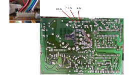
First I checked the voltages given to the PCB that goes to the CRT, the following image is what I got. all seem inside ranges (unless you guys tell me no), also verified that the voltage that the IC of the video amplifier system receives is correct (11.7 volts out of 12 expected).
Slide1.JPG

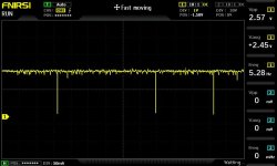
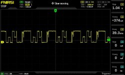
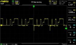
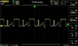
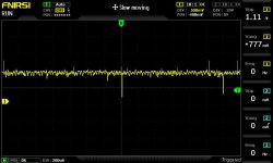
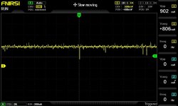
Then I use the oscilloscope to see the signal received by the PCB of the red, geen and blue data and also the vertical and horizontal ones. this are the images.

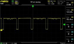
Vertical signal:
10.jpg

Horizontal signal:

11.jpg

Blue signal:


19.jpg

Green signal:
20.jpg

and Red signal:

21.jpg

If I test the input signals of the IC for the video amplifier system I get similar waves... the schematic is this:

Screenshot 2024-03-14 151833.png
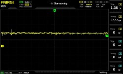
So, all the input voltages are correct (they require 12 volts), then I tested the output of the IC and see the wave forms.... the following are the blue, green and red images.

27.jpg

28.jpg


29.jpg


So that is the data I have at the moment.
Thank you, guys, for reading this, and I know my technical skills are not as great as yours, but I consider myself a quick learner, and would appreciate any input from you.
 
It appears that the IC is not working since it has RGB input signals but nothing else at its output. This does not mean the IC is faulty. Often IC 's like this appear faulty but it is due to one of the external components or signals being incorrect. So resist the urge initially at least to replace it.

Check that the power supply voltage is actually arriving at the IC power pins, also in an unpowered test, check the continuity of all of the inductors on the neck board and especially the low Ohmic value resistors, in case one in a power supply filter circuit has gone open circuit.

The H sync looks ok, but the V sync is way too high in frequency and irregular, it would be worth chasing that down.
 
Thank you for taking some of your time to answer Hugo.
Will check for that and will post here my results. ASAP
 
By the way, is it safe to turn on the monitor with the neck PCB disconnected? asking before doing something wrong. Thank you.
 
By the way, is it safe to turn on the monitor with the neck PCB disconnected? asking before doing something wrong. Thank you.
Generally, there is no diagnostic need to do that.

Remember the electrodes in the CRT (aside from the heater) do not draw any significant current, have an extremely low capacitance, and won't affect any measurements on the neck pcb to any great extent. Your meters will draw more current, except perhaps the cathode connections of the gun at full beam current.

You can leave the neck board off, if you wanted, but it has high voltages applied including the focus voltage, and then it is swinging around loose in the breeze. So if you do do it, (I have never needed to repairing hundreds of VDU's) make sure to wrap it up in a few plastic bags to insulate it. If it arcs over to the main pcb you will destroy parts on the neck board and likely multiple IC's in the main board.

(I wonder who suggested removing neck boards for some reason in VDU repair, while powering the VDU, it may be another one of those mis-guided youtube videos which seem so common on VDU repairs)

If you want to deactivate the CRT beam energy, say if there is vertical collapse and a bright horizontal line that won't extinguish with minimum brightness control setting and you are worried about phosphor damage, you can simply disconnect (usually a solder sucker on the pin to the CRT's heater) one connection to the heater and you will have no CRT beam current that way and leave the neck board exactly (safely) where it is.
 
Last edited:
I am not sure how close this schematic will be, but it uses the same LM1203 I.C.
 

Attachments

  • Acer - 7135C - Monitor - Schematic (1996).pdf
    378.5 KB · Views: 4
Wow Bburley, they do look almost like the monitor I have, mine was built in 1991 and it is model 7031, perhaps a bit modified version, but almost all seems in place. So, I decided to check some components and their numbers, my monitor in the PCB that goes to the neck has all the electrolytic capacitors numbered with hundred. This has them with 2hundred, and several do not seem to be the same. but it's a start. Thank you.
 
Last edited:
Ok I measured the resistance of all resistors in the neck board. These are the ones I found had a different resistance as expected ( I imagine some of these results are defective due to them still soldered but will post them here to analyze)

resistors defective.jpg


Resistor No. = Reported value in ohms (Expected value [min/max tolerance]) All tolerances are 5%.
R150 = 400.5 (430 [408/451])
R140 and R148 both = 1.6K (5.1K [4.8K/5.3K])
R155 = 0.7 ohms (50G [47.5G/52.5G])
R151 = 1 ohm (50G [47.5G/52.5G])
R154 = 0.6 ohms (1G [950M/1.04G])
R189 = 1.1K (1.5K [1.42K/1.57])
R184 = 1.5K (2.2K [2.09K/2.31K)])

The Neck PBC's IC (the video amplifier system) expects 12 volts and receives 11.7 in all voltage entries.

Thank you, all you guys, for reading this and trying to help fix this monitor!
 
The problem may have nothing to do with the neck board at all. As Hugo said, there is something very wrong with the vertical signal. This would be from IC201 and IC202 on the 7135 schematic.
 
There's a good chance the problem is related to all that corrosion. The adjustment pots look like they could be damaged, or dirty. The sub contrast control could cause no video if it was open circuit.

Since you have high voltage, I would try turning up the screen/g2 control (usually on the flyback below the focus control). No matter what the video circuit is doing, you should be able to get something on the screen. It might just be a blank raster with retrace lines, or there might be something on the screen to give you a clue.

What voltages do you measure on the cathodes? Those are labeled R, G, and B. Also G1, and G2 would be good to know. Do the R, G B, or G1 change at all when you adjust the brightness, or contrast controls?
 
Back
Top