Roger, going to check that vertical signal again, the weird part is that I think I measured it directly from the input cable, but going to double check that vertical portion of the circuit.The problem may have nothing to do with the neck board at all. As Hugo said, there is something very wrong with the vertical signal. This would be from IC201 and IC202 on the 7135 schematic.
Upcoming Events:
- VCF South West - June 14 - 16, Davidson-Gundy Alumni Center at University of Texas at Dallas
- VCF West - Aug 2 - 3, Computer History Museum, Mountain View, CA
- VCF Midwest - Sept 7 - 8 2024, Schaumburg, IL
- VCF SoCal - Mid February 2025, Location TBD, Southern CA
- VCF East - April 2025, Infoage Museum, Wall NJ
-
Please review our updated Terms and Rules here
You are using an out of date browser. It may not display this or other websites correctly.
You should upgrade or use an alternative browser.
You should upgrade or use an alternative browser.
Old monitor Acerview 11vga
- Thread starter Datamisc
- Start date
Hey Andy, Will check that and come back with the measurements.There's a good chance the problem is related to all that corrosion. The adjustment pots look like they could be damaged, or dirty. The sub contrast control could cause no video if it was open circuit.
Since you have high voltage, I would try turning up the screen/g2 control (usually on the flyback below the focus control). No matter what the video circuit is doing, you should be able to get something on the screen. It might just be a blank raster with retrace lines, or there might be something on the screen to give you a clue.
What voltages do you measure on the cathodes? Those are labeled R, G, and B. Also G1, and G2 would be good to know. Do the R, G B, or G1 change at all when you adjust the brightness, or contrast controls?
bburley
Experienced Member
I put little value on your resistance measurements due to them being made in-circuit. Unless you have a good board to compare in-circuit measurements looking for differences, it is too much thinking for my tired old brain 
There would also be added value in specifying EXACTLY where your measurements are taken from (pin x of component y). "Input Signal" is a bit too vague.
The video output signal could be clamped off if all of the input signals are not correct.
There would also be added value in specifying EXACTLY where your measurements are taken from (pin x of component y). "Input Signal" is a bit too vague.
The video output signal could be clamped off if all of the input signals are not correct.
Hugo Holden
Veteran Member
Since there appears to be an issue with the vertical sync signal, chase that down first.
The in-circuit resistance measurements look ok. An in-circuit test(if the resistor is ok) will either give the value of the resistor or a lower value due to currents in the circuits it is connected to while you are testing it. However, the resistor should never read significantly higher than the marked value, in an in circuit or out of circuit test.
The in-circuit resistance measurements look ok. An in-circuit test(if the resistor is ok) will either give the value of the resistor or a lower value due to currents in the circuits it is connected to while you are testing it. However, the resistor should never read significantly higher than the marked value, in an in circuit or out of circuit test.
andy
Experienced Member
It's possible that the monitor intentionally blanks the picture when it doesn't have valid sync signals.
I explored both PCB, there is nothing comparable with IC201 (TDA4858 Economy Auto sync Deflection Controller), and instead of the IC202 (TDA4865 Vertical deflection booster) I found the TDA1675A (Vertical Deflection Circuit)The problem may have nothing to do with the neck board at all. As Hugo said, there is something very wrong with the vertical signal. This would be from IC201 and IC202 on the 7135 schematic.
The other ICs in the monitor are: LM1203N (Video amplifier System), SN74LS86N (Quad 2-Input Exclusive OR Gate), MC1291P (TV Horizontal Processor), UC3842 (Current-mode PWM Controller), and CNY17-2 (Digital Logic Isolator and power supply feedback control).
The TDA1675A (Vertical Deflection Circuit) PIN Connections are as follows:
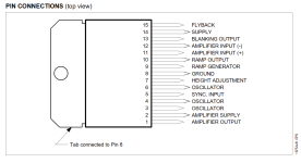
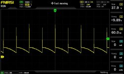
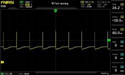
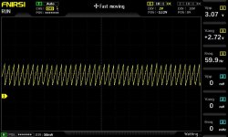
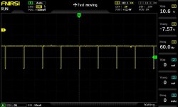
The following images are from the oscilloscope checking each pin in order:
1 - Amplifier Output:
2 - Amplifier supply:
3 - Oscillator
4 - Oscillator
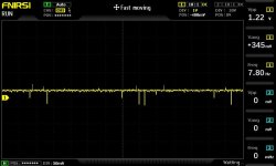
5 - Sync Input
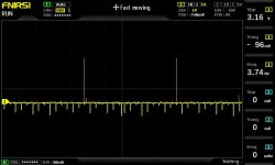
6 - Oscillator
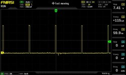
7 - Height Adjustment
8 - Ground (posting all)
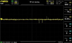
9 - Ramp Generator
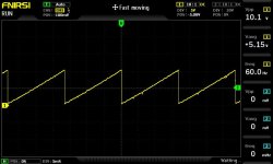
10 - Ramp outputThe problem may have nothing to do with the neck board at all. As Hugo said, there is something very wrong with the vertical signal. This would be from IC201 and IC202 on the 7135 schematic.
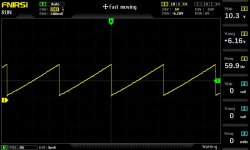
11 - Amplifier Input(+)
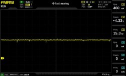
12 - Amplifier Input (-)
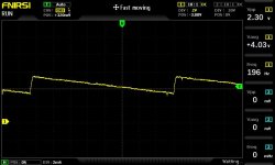
13 - Blanking Output
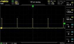
14 - Supply
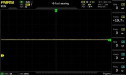
15 - Flyback
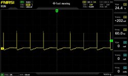
Thank you bburley.
If I send you a picture, could you point me around the correct area of the g2 control? Thank you AndyThere's a good chance the problem is related to all that corrosion. The adjustment pots look like they could be damaged, or dirty. The sub contrast control could cause no video if it was open circuit.
Since you have high voltage, I would try turning up the screen/g2 control (usually on the flyback below the focus control). No matter what the video circuit is doing, you should be able to get something on the screen. It might just be a blank raster with retrace lines, or there might be something on the screen to give you a clue.
What voltages do you measure on the cathodes? Those are labeled R, G, and B. Also G1, and G2 would be good to know. Do the R, G B, or G1 change at all when you adjust the brightness, or contrast controls?
I did some measurements on the R, G, B, G1 and G2 with low contrast and brightness and then high contrast and brightness. these are the oscilloscope images:
B with controls in low
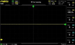
B with controls in high
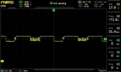
R with low
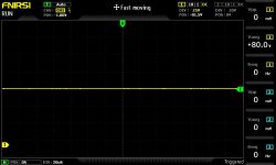
R with High
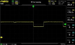
G2 with both low and high in the controls
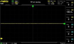
G with Low
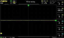
G with High
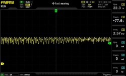
G1 with low
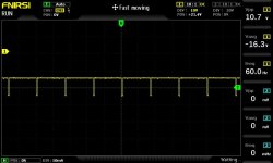
G1 with High
Thank you, Andy.
bburley
Experienced Member
What triggered the curiosity about the vertical circuit is your earlier post on March 14 where the scope image of the "vertical" signal was only 5.28 Hz (60 Hz expected) and looked erratic.
Now when you scoped pin 5 of the TDA1675A (sync input) it also appears wrong at 3.74 Hz. There isn't enough pulses showing to see if it looks erratic or not.
Your scope is set to 50ms per division, so the detected frequency looks correct. 60Hz pulses should be spaced about 16.7ms apart.
Are you sure that the video card in the computer is compatible with this monitor. I don't recall you saying what kind of video card you were using.
Thank you for reading this Burley.What triggered the curiosity about the vertical circuit is your earlier post on March 14 where the scope image of the "vertical" signal was only 5.28 Hz (60 Hz expected) and looked erratic.
Now when you scoped pin 5 of the TDA1675A (sync input) it also appears wrong at 3.74 Hz. There isn't enough pulses showing to see if it looks erratic or not.
Your scope is set to 50ms per division, so the detected frequency looks correct. 60Hz pulses should be spaced about 16.7ms apart.
Are you sure that the video card in the computer is compatible with this monitor. I don't recall you saying what kind of video card you were using.
The monitor has been tested using the original graphics card in the old 386 computer that it came with. the Acumos AVGA1 (aka Cirrus Cl-GD5401), I have also tested the monitor using the VGA Monitor Tester from PCBJunkie.net ( https://pcbjunkie.net/index.php/projects/video-testers/vga-test-dongle/ ), and also with an old ATI Rage XL 8mb PCI VGA in 640x480 resolution at 60Hz with 8bit color, and I get no image with either of them.
I have another VGA monitor, a Compaq one, which does renders correctly using those cards.
Last edited:
bburley
Experienced Member
I don't know how easy it will be to follow the sync signal from the vertical circuit back to the VGA connector without a proper schematic, but I would start by verifying that there is proper vertical sync coming into the monitor from the VGA connector and check it again where the wire connects to the main circuit board of the monitor. Then what is between there and the sync input pin of the TDA1675A is a good question.
Another thing that I would be tempted to try it to connect a working monitor to the computer and try for a lower resolution setting, then switch back to the non-working monitor. Is it possible that the current setting is out of range for the Acer monitor? Could the monitor be old enough to not even support 640x480?
Another thing that I would be tempted to try it to connect a working monitor to the computer and try for a lower resolution setting, then switch back to the non-working monitor. Is it possible that the current setting is out of range for the Acer monitor? Could the monitor be old enough to not even support 640x480?
bburley
Experienced Member
You might have to get datasheets for each IC and try to follow the vertical sync signal path. Perhaps there is another IC doing sync processing.
Will work on that ASAP and will post it here, although I think I am working at the correct resolution but it did support 640x480, I remember doing some low level ASM programming in graphics in my teens, double checking never hurts.You might have to get datasheets for each IC and try to follow the vertical sync signal path. Perhaps there is another IC doing sync processing.
Thanks.
bburley
Experienced Member
Excellent. Will check it out. Thank you.I found a schematic for an Acer m/n 7033 - Maybe this is closer.
bburley
Experienced Member
andy
Experienced Member
When I said to measure the voltages on the cathodes, G1, and G2, I just mean to use a volt meter. At this point, we're just trying to figure out why the screen isn't lighting up. It's wise to check voltages with a meter before connecting your oscilloscope probe to a CRT because there are high voltages there that could damage it. The G2 looks suspicious. Normally it's more like 500v. If it's really only 80v, I would expect the screen to be black.
Hugo Holden
Veteran Member
I agree .When I said to measure the voltages on the cathodes, G1, and G2, I just mean to use a volt meter. At this point, we're just trying to figure out why the screen isn't lighting up. It's wise to check voltages with a meter before connecting your oscilloscope probe to a CRT because there are high voltages there that could damage it. The G2 looks suspicious. Normally it's more like 500v. If it's really only 80v, I would expect the screen to be black.
Both the focus and G2 voltages are sourced from the EHT, the focus potential could be 5kV or more and the G2 maybe around 500v. Also, the G2 being in the lower leg of the voltage divider, the source resistance there is unlikely to be more than a few Meg Ohms, so if it only reads 80V with a typical DVM (that has a 10 Meg input resistance) this implies that the EHT itself must be very low (assuming the voltage divider chain has not failed). And one would expect the CRT to be blacked out.
oh, ok, gotcha, thank you Andy. Will double check those values with the multimeter then and post the results here.When I said to measure the voltages on the cathodes, G1, and G2, I just mean to use a volt meter. At this point, we're just trying to figure out why the screen isn't lighting up. It's wise to check voltages with a meter before connecting your oscilloscope probe to a CRT because there are high voltages there that could damage it. The G2 looks suspicious. Normally it's more like 500v. If it's really only 80v, I would expect the screen to be black.
