voidstar78
Veteran Member
For the IBM 5100/5110 there are two "styles" of CRTs. The MIM describes them as "with horizontal linearity sleeve" or without (PDF page 51, or 2-33 / 247).
I have a 5110 with tthe "horizontal linearity sleeve" style (which has more differences than just the sleeve part) - it happens to be a 1978 build of a 5110, but I'm not sure if that style of CRT is really older relative the other style or not. (I have another 5110 with that other style, which is working fine - I think both styles were used across production of both 5100 and 5110's).
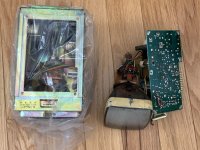
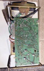
Since this CRT isn't working, I'm taking it out and sharing a little bit about what the "other side" looks like. And I think this CRT is quite dead, but maybe someone has some suggestions on things to try.
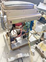
Just 3 screws removes the CRT. I leave the 4th one attached to the ground wire (but it is detached from the CRT itself, and the ground is between the main system power input and the bracket used for the audio speaker). In other words, aside from the 10 small connector wires on the side, the CRT is standalone.
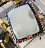
Here is why I think this CRT is dead... There is quite a bit of "bruising" around the edge of the display, along with the "shotgun scatter" around the center that I've seen on several other 5110's. These "bruises" aren't shadows from taking the photo, but dark spots within the CRT glass itself. Then beyond that, when powering on, nothing appears on the CRT - no change in hue or intensity, nothing to indicate that anything is trying to be drawn on the glass at all (and I tried adjusting the brightness and vert/horz sync).
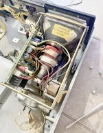
And here's the "rarely seen" bottom of the CRT. On the right is the only connector, which is blue and reminds me of the Commodore-style connectors. This one has 10-pins.
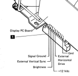
Per the MIM, those pins are as follows: (I assume the same pins for either style of CRT) I verified I had about 0.8V on the Brightness pin, and did have +12V on pin 7 -- so this CRT was getting power.
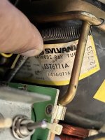
The sticker on this particular CRT reads
GTE Sylvania CRT
type 5ST6111A
part no. 1-014-0716
CODE 2-739
It is also labeled as Ball Brother Research Corporation model "TV-5". Also labeled as IBM part number 1608865 EC832674.
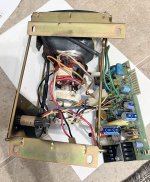
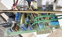
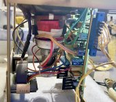
And here is also why I won't spend too much time trying to "save" this CRT: the center piece (the red wounds of wire) is completely loose, it spins fairly freely, and there are gaps between the bottom and top. I don't know too much about CRT, but seems there are magnets and a vacuum involved, and none of that is secured in place here. Plus notice the "suction cup" piece (top left) has had some substance oozed out. However, the PCB looks OK (no apparent burn marks anywhere). I'm not sure if those are original caps, but it seems the original clips are in place that secure the PCB to the bracket (you'd have to cut those clips to get it off - you can see one of them in the bottom right of the image below - unless maybe those are replaced clips already?).
NOTE: The MIM does talk about if the display is tilted, rotating the entire "yoke" (but involves breaking some seals and re-gluing things). So maybe the "loose-ness" of this piece is normal, or that was attempted in its past. But just checking that the 12V was getting into the PCB (which it is), that's about as far as I'm comfortable troubleshooting on this CRT :D
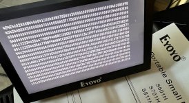
Note that the IBM 5100/5110 have an external BNC connector, and that is still working on this unit. So with that, I don't really need this working CRT, I can use the system with the external monitor. I've also found small 5" flat screens with BNC inputs, I've thought I could remove this CRT, and substitute in a modern 5" panel (then routing that BNC cable internally).
I have a 5110 with tthe "horizontal linearity sleeve" style (which has more differences than just the sleeve part) - it happens to be a 1978 build of a 5110, but I'm not sure if that style of CRT is really older relative the other style or not. (I have another 5110 with that other style, which is working fine - I think both styles were used across production of both 5100 and 5110's).
Since this CRT isn't working, I'm taking it out and sharing a little bit about what the "other side" looks like. And I think this CRT is quite dead, but maybe someone has some suggestions on things to try.
Just 3 screws removes the CRT. I leave the 4th one attached to the ground wire (but it is detached from the CRT itself, and the ground is between the main system power input and the bracket used for the audio speaker). In other words, aside from the 10 small connector wires on the side, the CRT is standalone.

Here is why I think this CRT is dead... There is quite a bit of "bruising" around the edge of the display, along with the "shotgun scatter" around the center that I've seen on several other 5110's. These "bruises" aren't shadows from taking the photo, but dark spots within the CRT glass itself. Then beyond that, when powering on, nothing appears on the CRT - no change in hue or intensity, nothing to indicate that anything is trying to be drawn on the glass at all (and I tried adjusting the brightness and vert/horz sync).

And here's the "rarely seen" bottom of the CRT. On the right is the only connector, which is blue and reminds me of the Commodore-style connectors. This one has 10-pins.

Per the MIM, those pins are as follows: (I assume the same pins for either style of CRT) I verified I had about 0.8V on the Brightness pin, and did have +12V on pin 7 -- so this CRT was getting power.

The sticker on this particular CRT reads
GTE Sylvania CRT
type 5ST6111A
part no. 1-014-0716
CODE 2-739
It is also labeled as Ball Brother Research Corporation model "TV-5". Also labeled as IBM part number 1608865 EC832674.
And here is also why I won't spend too much time trying to "save" this CRT: the center piece (the red wounds of wire) is completely loose, it spins fairly freely, and there are gaps between the bottom and top. I don't know too much about CRT, but seems there are magnets and a vacuum involved, and none of that is secured in place here. Plus notice the "suction cup" piece (top left) has had some substance oozed out. However, the PCB looks OK (no apparent burn marks anywhere). I'm not sure if those are original caps, but it seems the original clips are in place that secure the PCB to the bracket (you'd have to cut those clips to get it off - you can see one of them in the bottom right of the image below - unless maybe those are replaced clips already?).
NOTE: The MIM does talk about if the display is tilted, rotating the entire "yoke" (but involves breaking some seals and re-gluing things). So maybe the "loose-ness" of this piece is normal, or that was attempted in its past. But just checking that the 12V was getting into the PCB (which it is), that's about as far as I'm comfortable troubleshooting on this CRT :D

Note that the IBM 5100/5110 have an external BNC connector, and that is still working on this unit. So with that, I don't really need this working CRT, I can use the system with the external monitor. I've also found small 5" flat screens with BNC inputs, I've thought I could remove this CRT, and substitute in a modern 5" panel (then routing that BNC cable internally).
Last edited:

