SteveG
Experienced Member
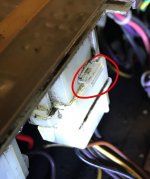
I am stuck disconnecting the Power Supply from the body of my 11/34 !
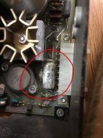
As well as the usual plastic side locks there is a metal clip sticking out of the side of the connector (see photo).
It would help if anyone knows:-
1) If this clip could be preventing me from releasing the cable?
2) What is it’s purpose of this clip as it is not keen to move in and out
As well as the usual plastic side locks there is a metal clip sticking out of the side of the connector (see photo).
It would help if anyone knows:-
1) If this clip could be preventing me from releasing the cable?
2) What is it’s purpose of this clip as it is not keen to move in and out