• Please review our updated Terms and Rules here

30€ Intel Intellec MCS 8 8080 restoration

Magnedyne

Member
Joined
Sep 27, 2023
Messages
36
Location
Laupheim, Germany
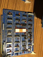
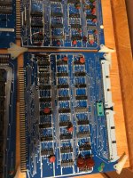
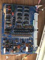
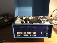
I recently picked up this Intellec 8 (8080) in frankly amazing condition for just 30€. It was purchased and imported to Germany by Siemens in 1974. Due to it still having its 110V volt eprom power supply I believe it to be unused. It even came with the male Current loop plug as well as the 37pin male interface plugs, both have never had cables attached.
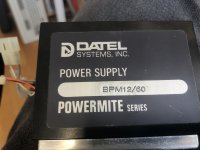
The left (in my case 5V;?) power supply seems to be missing. Maybe they were in the process of converting it to 240V when the project was shelved, who knows.
I could really use some detailed pictures of the power supply’s of other Intellecs.
IMG_6426.jpeg
Regarding the Voltages i require a little help as well, what’s 5V i know but the rest is a mystery so far.
image.jpg

I’ll keep you updated.
Cheers
 
Last edited:
Here are some pictures of all the Cards.
I’ve got one Rom card, two RAM cards, a CPU card, an interface card, an Eprom programmer card and the front panel controller.
 

Attachments

  • IMG_6573.jpeg
    IMG_6573.jpeg
    2.3 MB · Views: 7
  • IMG_6572.jpeg
    IMG_6572.jpeg
    2.1 MB · Views: 7
  • IMG_6571.jpeg
    IMG_6571.jpeg
    2.1 MB · Views: 8
  • IMG_6568.jpeg
    IMG_6568.jpeg
    2.6 MB · Views: 8
  • camphoto_1903590565.jpeg
    camphoto_1903590565.jpeg
    4.8 MB · Views: 5
  • image.jpg
    image.jpg
    2.3 MB · Views: 7
As I mentioned previously, one of my power supply’s is missing. The other one might just have been converted to 240V already. There is another power supply electrically „in font“ of the original transformers, however I haven’t figured out what it does yet.
 

Attachments

  • camphoto_341603450.jpeg
    camphoto_341603450.jpeg
    2.9 MB · Views: 9
It cleaned up really well, was just a bit dusty after all. I’ll most likely pair it with my ADM-3 even though they’re 2 years apart. Looks good imo.
camphoto_1251336619.jpeg
If I manage to get an ASR one day it’ll most likely go with the intellec.
 

Attachments

  • IMG_6567.jpeg
    IMG_6567.jpeg
    2.2 MB · Views: 8
Mine is also 110VAC only. This is how the PSU looks like. A linear open frame PSU. It is mounted to a square piece of aluminium which attaches to the frame.
3BAD2C77-AC0B-4854-8AD4-D9627F672A06.jpeg
The one I have is s/n 178.

Your board seem to have a v1.0 monitor. Could be interesting to check if it is the same as the version 1.0 mentioned here.

My machine has version 4.0 and I interfaced it to a Facit paper tape reader and Facit paper tape punch using the second I/O board.

 
Mine is also 110VAC only. This is how the PSU looks like. A linear open frame PSU. It is mounted to a square piece of aluminium which attaches to the frame.
View attachment 1266608
The one I have is s/n 178.

Your board seem to have a v1.0 monitor. Could be interesting to check if it is the same as the version 1.0 mentioned here.

My machine has version 4.0 and I interfaced it to a Facit paper tape reader and Facit paper tape punch using the second I/O board.

The psu pictured is the one also responsible for 5v right?
which connectors and voltages does it have/ output where?
regarding the Roms, I unfortunately havent got a compatible eprom reader.
I own a Facit reader and punch as well, I’ll attach some pictures here later.
 
Yes. This PSU only do the 5V. That is the only PSU in the left compartment.
The other psu, as mentioned previously, I’m not sure if mine has been converted to 240V. If it’s not too complicated, could you please provide me with pictures of the other psu as well?
Taking a look at the schematic for the Backplane it states that +/-12 are connected to the Molex connector on the backplane as well. Are you sure the left psu does only 5V? If it does, do the +/-12 get introduced into the backplane from the right PSU through the Prom Programmer card? Unfortunately I don‘t own a Variac, therefore I can’t really test this myself.
In my unit the right PSU looks like this, I suspect the mysterious Datel PSU which is electrically in front of the original Transformers to be 240->110V.
1307733B-2A7B-4E05-8145-6FDFDD7693A5.jpeg1AE14481-2F2A-478B-BD3C-4442CB6DD702.jpeg
thanks in advance
 
Last edited:
Alright I have studied the schematics a bit more and most of my questions have been answered. (Regarding the 12V they are there on paper but since they’re not required by anything they don’t seem to exist in reality. My theory of the unit having been partially converted to 240 also turned out to be wrong, the mysterious Datel PSU likely rectifies the 50VAC into 80VDC.)
Edit: the Datel unit likely outputs 12V/60mA
The 9V are still a mystery though. I’m guessing they are supplied by the right supply via the Prom Card.
 
Last edited:
Alright I have studied the schematics a bit more and most of my questions have been answered. Regarding the 12V they are there on paper but since they’re not required by anything they don’t seem to exist in reality. My theory of the unit having been partially converted to 240 also turned out to be wrong, the mysterious Datel PSU likely rectifies the 50VAC into 80VDC.
The 9V are still a mystery though. I’m guessing they are supplied by the right supply which also outputs 10VDC via the Prom Card.
80 V DC sounds really odd. I've found a BPM 15/50 which produces +-15 V DC at 50 mA from a 120 V AC input. If the nomenclature follows logic, 12/60 would then produce +-12 volts at 60 mA.

edit; Found the specification from my favourite document archive. The power supply is indeed +-12 volts at 60 mA. Link:


Page 168.
 
Last edited:
60 V sounds really odd. I've found a BPM 15/50 which produces +-15 V DC at 50 mA from a 120 V AC input. If the nomenclature follows logic, 12/60 would then produce +-12 volts at 60 mA.
Makes sense, input would be 110V in that case. I haven’t got the unit in front of me right now, I’m at school, so I could only take a guess. But yeah that would make more sense. I haven’t been able to remove the PSU yet so I couldn’t check it directly with a Voltmeter. I’ll need a longer and thinner screwdriver first.
I’ll take out everything, hook it up to 110 and check the Outputs this evening. If I’m lucky it’ll all just work. I haven’t got a Variac so I’ll be reforming the big capacitor externally.
 
Last edited:
What do you mean by input being 25/50/110 volts? See the page 169 of the linked document for the input voltage possibilities of the Datel PSU, it's either 100 or 220 volts +-10 %.
 
The 5V PSU is easy to replace luckily. The +80/50AC/… is a bit more complicated but should be doable as well if it turns out to be beyond saving, I doubt this however. Anything can be fixed with enough effort.
 
Last edited:
80V (or whatever it really is) is only used for 1702 programming. If you don’t plan to program any 1702 then it is not necessary. As far as I remember is just consists of a small transformer and a capacitor. The rectifier is on the EPROM programmer board if I remeber correctly.

Here is a link to both pictures and ROM dumps: https://drive.google.com/drive/folders/1NOUxgHN0HNzZujf-OtU8pmPDZS40e1zJ

I think the -9V is used for 1702 EPROMs, but also regulated down to -5V to feed the CPU substrate bias.

Btw. Happen to see this. https://www.ebay.com/itm/256253200488
Someone actually paid 1495 dollar for the CPU card alone. Crazy. You paid 30 euros for all of it…
 
Back
Top