Slob
Experienced Member
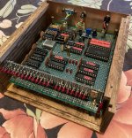
On my “bucket list” was building a 4004 single board computer. I’ve collected the parts over the years but have tried to use them and generally failed. Over the last few years, Github projects popped up that made this fairly easy and productive. I couldn’t decide which to build so I wire wrapped both of them.
The first, designed by Jim Loos (at https://github.com/jim11662418/4004-SBC), was fairly straightforward to build and didn’t need any unusual parts besides the 400x family chips (but see below). The firmware included tic-tac-toe and number guessing. Arithmetic and I/O port examples are also included in the menu-driven system. Some small modifications I made to the hardware were the use of a DC-DC converter hidden on the back of the board, optional use 4002-2 and 4040 sockets, and the use of a 2764. You can’t add the 4002-2’s without modifying the setup of the 4265 to four input ports in the firmware.
The second (and considerably more complex) project was by Ryo Mukai of Japan (at https://github.com/ryomuk/test4004). This uses external non-400x family, +5V logic based RAM (paged, yet). The RAMs were a bit tricky to find; I used Jim’s RS-232 hardware and a 27C256 due to parts availability (parts in my house); I used a 4201 clock generator; there is a 4040 socket; a DC-DC converter was also used for the +5/-10 from 12V wall wart input. I added the 4265 from Mr. Loos’s design but this is not used in the stock firmware. The stock firmware does floating point math fairly well and also does square root calculations to 15 or 16 digits, very, very cool (but not very fast!). While I was doing this, he updated the project to use bigger RAMs and actually wrote an 8080 emulator that runs on the 4004 (VERY slowly, but can run Tiny and otherwise BASIC). Crazy, but absolutely amazing!
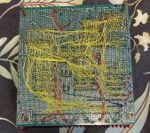
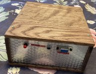
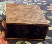
I built quickie oak/stained frames for them with Lexan backs to “display” the wire wrapping. The 4040 CPU's, as expected, run the firmware on both boards perfectly (although you need to remove the 4004’s first, of course). The sockets are high quality machine pin - I learned the “good socket” lesson long ago. I have wire wrapped projects almost 25 years old that still work fine with this type of socket, untouched!
At first, I didn’t have the proper crystals for these projects (and apparently neither did Mr. Loos). Incredibly, I bid on, and won, a bag of 100 on eBay at a silly low price, actually lower than Q1 price from someone else. So now, I have a “lifetime” supply of proper CTS 5.185 Mhz crystals for the 4004/4040. If anyone plans on actually building a 4004 or 4040, I can send you some, PM me (while supplies and/or I last, ha ha). If Mr. Loos or Mr. Mukai read this forum, some are reserved for you, although I can ship them in the US only.
Interesting point in making “retro” looking projects. “Period”, large diameter 0.1 uF disk bypass capacitors (big like they once were, in the 60’s to 80’s) are apparently getting thin on the ground and expensive once you find them.


The first, designed by Jim Loos (at https://github.com/jim11662418/4004-SBC), was fairly straightforward to build and didn’t need any unusual parts besides the 400x family chips (but see below). The firmware included tic-tac-toe and number guessing. Arithmetic and I/O port examples are also included in the menu-driven system. Some small modifications I made to the hardware were the use of a DC-DC converter hidden on the back of the board, optional use 4002-2 and 4040 sockets, and the use of a 2764. You can’t add the 4002-2’s without modifying the setup of the 4265 to four input ports in the firmware.
The second (and considerably more complex) project was by Ryo Mukai of Japan (at https://github.com/ryomuk/test4004). This uses external non-400x family, +5V logic based RAM (paged, yet). The RAMs were a bit tricky to find; I used Jim’s RS-232 hardware and a 27C256 due to parts availability (parts in my house); I used a 4201 clock generator; there is a 4040 socket; a DC-DC converter was also used for the +5/-10 from 12V wall wart input. I added the 4265 from Mr. Loos’s design but this is not used in the stock firmware. The stock firmware does floating point math fairly well and also does square root calculations to 15 or 16 digits, very, very cool (but not very fast!). While I was doing this, he updated the project to use bigger RAMs and actually wrote an 8080 emulator that runs on the 4004 (VERY slowly, but can run Tiny and otherwise BASIC). Crazy, but absolutely amazing!
I built quickie oak/stained frames for them with Lexan backs to “display” the wire wrapping. The 4040 CPU's, as expected, run the firmware on both boards perfectly (although you need to remove the 4004’s first, of course). The sockets are high quality machine pin - I learned the “good socket” lesson long ago. I have wire wrapped projects almost 25 years old that still work fine with this type of socket, untouched!
At first, I didn’t have the proper crystals for these projects (and apparently neither did Mr. Loos). Incredibly, I bid on, and won, a bag of 100 on eBay at a silly low price, actually lower than Q1 price from someone else. So now, I have a “lifetime” supply of proper CTS 5.185 Mhz crystals for the 4004/4040. If anyone plans on actually building a 4004 or 4040, I can send you some, PM me (while supplies and/or I last, ha ha). If Mr. Loos or Mr. Mukai read this forum, some are reserved for you, although I can ship them in the US only.
Interesting point in making “retro” looking projects. “Period”, large diameter 0.1 uF disk bypass capacitors (big like they once were, in the 60’s to 80’s) are apparently getting thin on the ground and expensive once you find them.