- VCF South West - June 14 - 16, Davidson-Gundy Alumni Center at University of Texas at Dallas
- VCF West - Aug 2 - 3, Computer History Museum, Mountain View, CA
- VCF Midwest - Sept 7 - 8 2024, Schaumburg, IL
- VCF SoCal - Mid February 2025, Location TBD, Southern CA
- VCF East - April 2025, Infoage Museum, Wall NJ
-
Please review our updated Terms and Rules here
You are using an out of date browser. It may not display this or other websites correctly.
You should upgrade or use an alternative browser.
You should upgrade or use an alternative browser.
5.25 floppy repair (plastic part missing).
- Thread starter flaviosr
- Start date
1944GPW
Veteran Member
I'm going to guess a workalike cam might look something like the following.

If it does, then the following OpenSCAD could help. Download from openscad.org then paste the following into the text area then press F5 to view, F6 to render, then F7 to save the STL model.
Use calipers to measure the shaft diameter, cam length from the scratch marks and plug in the measurements into the top variables. Print one and if it doesn't close enough then bump the cam diameter up a mm or two.
We don't see the door lever orientation in your photo so if it's out of opening/closing phase then set ORIENTATION to 90 or whatever.
Code:
// Floppy drive lever cam
// The following are guesses only. Measure shaft dia etc. with calipers
CAM_DIA = 9;
CAM_LENGTH = 10;
SHAFT_DIA = 3;
OFFSET = 2;
ORIENTATION = 0;    // door lever phase to shaft flat

flatBlock=10;

FACETS=187;
$fn = FACETS;

difference()
{
    cylinder(d=CAM_DIA, h=CAM_LENGTH);
    translate([OFFSET, 0,0])
    {
        rotate(ORIENTATION)
           difference()
           {
               cylinder(d=SHAFT_DIA, h=CAM_LENGTH);
               translate([-(SHAFT_DIA/3)-flatBlock, -flatBlock/2, 0])
                   cube([flatBlock, flatBlock, CAM_LENGTH]);
           }
    }
}
Last edited:
Hugo Holden
Veteran Member
Another easy way to make that is on a small Lathe with a independent 4 jaw chuck to create the offset hole. Simply drill a hole for the shaft and then fit two grub screws to lock the cam to the flat on the shaft in the same way many knobs are locked onto flats on shafts. At least that is the way I would do it, because I have a lathe but not a 3D printer.
flaviosr
Experienced Member
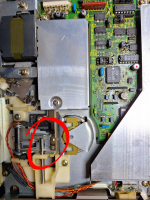
I have a 3D printer but I fear it's not a possible solution as you can see in the attached photo.
I do not have a lathe and I would be afraid making a bore on the shaft, afrait to weaken it too much.
I was thinking about cutting the shaft to free the "reduced part" (I do not know the word in English) but, again, I would not like to make permament mods.
I do not know if there are strong enough glues...
Attachments
1944GPW
Veteran Member
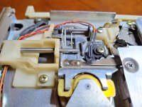
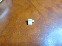
We now have some more information not proffered before. So that paddle cam is the "missing" piece? And that the shaft flat isn't extended to the end, highly likely the cam piece was molded on.
If that is the cam you have, then (what I would do myself) is unscrew the door latch shaft bracket at left. It doesn't have to come out of the front bezel, but enough to get clearance to the cam.
I would wash cam and shaft with IPA then file/cut two tiny notches on the short side and another two on the back of the cam, each at 1/4 the width in from the sides.
Then epoxy and clamp the cam back on the shaft so the broken edges are brought together. This is not enough to fix it, it is only to close and locate the cam.
After curing, I would make two bindings with Kevlar thread seated in the notches and tightly wound around, set the final looping with superglue and trim the Kevlar with an Exacto knife.
The thread will be below the outer sweeping edge of the cam where it contacts the plate. Then finally seal with a very light coat of epoxy.
Binding is for me the go-to method when the broken surfaces do not present enough area to glue, especially in a slippery material like Acetal, Nylon, HDPE, UHMWPE etc. and can I believe result in a repair that may be stronger than the original.
Well that's what I'd do. Good luck on your chosen repair path.
Last edited:
Someone
Experienced Member
Do it the old fashioned way: make a cast plug from the broken piece, infill the missing bits and make a new one out a material that can handle the torque.
pbirkel@gmail.com
Veteran Member
Except that this part appears to have been created directly onto the rod, not attached as a separate piece. Don't see how your method would apply.
I've done a little work with casting replacement parts. If removing the screws gets the shaft loose enough to give your room to work you could make a silicone mold with the broken part on a shaft. Cut mold to make it two part mold to get the existing part out then put mold on the shaft holding parts together and fill with resin. I had problems with air bubbles messing things up so may not be easy.Except that this part appears to have been created directly onto the rod, not attached as a separate piece. Don't see how your method would apply.
The other option I was thinking was 3D print the part but make one side good fit to shaft but then make it bigger and non round so after you fit the 3D part to the shaft you can inject some epoxy in from that side and tight fit on other side will prevent it from running out. The flat on the shaft and non round hole in the part should lock the part in place. Never done anything like this so can't say it will work.
flaviosr
Experienced Member
I have the idea of printing a similar pieces but longer and with circular bore.
I would leave two bores in the cam where there is the flat shaft zone, bores where I would put a metal piece (stronger than plastic).
I have to design it with Fusion and I am going to share it as soon as I have it (I have to leave for work and I do not want to bring with me the FDD).
The question is... do you think a 3D PLA printed part would withstand the torque? I was thinking about making the cam longer for this reason!
1944GPW
Veteran Member
Another idea that might work is to ditch a plastic cam replacement for metal.
First remove the shaft and bracket from the drive, take a measurement of the distance of the flat from the shaft end and also its orientation to the handle.
A scrap of aluminium say 12mm wide x 12mm long x 5mm thick could be cross-drilled through the thickness face close to one edge for the shaft diameter.
Then lightly superglue the metal cam on to position it.
On a hard surface use a small 2mm or 3mm diameter pin punch with hammer to stake/swage the cam piece on the shaft, at the measured location of the flat.
Lastly, file the outer edge corner to round where it will contact the plate. Reassemble and use a dab of lithium or ceramic grease on the sweep surface.
EDIT: pretty much what Hugo described earlier, but using swaging rather than grubscrews.
Last edited: