• Please review our updated Terms and Rules here

Another Atari 850 Question: Capacitors

clh333

Veteran Member
Joined
Feb 22, 2015
Messages
1,443
Location
Cleveland, OH, USA
In testing the unit I found that it would power up, given a 9VAC supply, but when measuring the nominal +5VDC output on the "parallel" port I found it to be 4.56 VDC. This is within range, for TTL signal purposes, but less than ideal.

I have a suspicion that the root of the problem lies in the capacitors associated with rectification, a couple of 2200 uF Nichicon electrolytics that must be 40 years old by now. I'd like to ask for some advice: Whether to replace them or leave them be?

Thanks for your replies,
-CH-
 
Old capacitors don't necessarily mean bad capacitors. I would say pull them off the logic board and put them in a LCR and/or component tester to see if they're good or not. If you don't have either of those and you question them, you can just replace all of the capacitors to have a known working set of them.

When testing a capacitor, the two most important values are the capacitance and ESR. If either one of those is too far off, it's going to cause problems.
 
Thank you for your reply. I do have an LCR meter and an ESR meter, albeit one for smaller values, but given the age and relative rarity of the board, plus my ability to damage anything, I was wondering if I should say "close enough" and leave it alone.

I was wondering about the issue, though, after my experience with another device, an X-10 CP 290 controller, which is designed to send control signals through household wiring. This controller also dated back to the '80s and was no longer functional. I read an article in which the writer described his procedure to revive one of these controllers, and he stated that he began to suspect the output filter capacitors in the rectifier. He said he found them passing significant amounts of AC and replaced them immediately. Following his advice (and yours) I replaced all the capacitors and restored the unit to operation.

-CH-
 
A 'scope on the power supply output would show the amount of ripple. What does your Atari use for a voltage regulator? Alternatively, set your DMM for AC volts and see what the reading settles down to.

Nichicon is a good old Japanese brand. They might be fine. On the other hand, replacing them on such an old bit of equipment should be pretty straightforward. A related question: When the system is on, what does the output of your 9V power supply sag to?
 
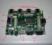
Thank you both for your guidance. The attached photo will illustrate my answers to your questions:

The (nominal) 9VAC power supply measures 10.99 VAC at the jack (D) with the power switch off. with the switch on the measurement drops to 10.66 - not a great loss, evidently. There are two 7805 regulators on board (E), one with and one without a heat sink. Measured across one end of the Nichicon pair (A) the AC voltage fluctuates too much to take a settled reading. Measured across the other end (B) the AC reading is 0.003. Guess that answers that.

C is a diode array, F are the two SIO-bus ports and G is the parallel port. There are four RS-232 ports; only the first has a full complement of signals. Interestingly the fourth RS port is designed for a 20 mA current loop.

Thanks again for your help.

-CH-

Click image for larger version  Name:	Atari 850 Board.jpg Views:	0 Size:	243.5 KB ID:	1236415
 
Back
Top