It's been a while - almost a year since I posted above. In case anyone was interested, or also working on an M24 PSU, here's a report/blog post on fixing my M24 PSU. It hasn't been my "main project" (I'm mainly into 8bit systems

), and I needed several sessions for this PSU. Multiple times I put the whole thing away for months. But finally, it's as good as new.
The ugly issue with my PSU was, it wasn't completely broken. It kind of worked - but only delivered less than half the power, that it should normally be capable of. Worse than that: it just wouldn't start when a high load was connected. It would start with nothing or only a light load connected - and it kept working when a high load was connected with a delay... That's not the expected behaviour, of course, and it wasn't enough to power the M24. In fact, as stated in the M24 "Theory of Operation" manual, the PSU should actually be capable of briefly exceeding its regular maximum power output at start up. Such a weak PSU is worse than a completely broken one: it means none of its components is completely dead, and narrowing down a fault isn't quite so obvious.
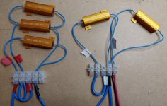
So, I built a small test rig to test the PSU without the M24. For the loads, I used beefy 50W resistors of various values (1-10 Ohm):

I grabbed a bunch of such resistor values from an discount online shop for a few bucks (Euros). I used several of these in parallel to adjust the load for each voltage rail - and to test different load levels. The resistors will get warm/hot - so distributing the load to several resistors makes sense anyway. I mounted the resistors to a large wooden panel. And also mounted the two M24 PSU boards onto the a panel (with isolated/plastic standoffs), so everything was securely fastened, nothing flopping around - and the PCBs were easily accessible.....
As a word of warning, concerning "easily accessible": don't mess with PSUs if you don't know what you're doing or don't know the proper safety procedures for working with high voltages.
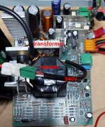
One of the two M24 PSU boards takes care of the primary/high voltage side, and the the other mainly of the secondary/low-voltage side, however, both boards are dangerous: the high voltage/high frequency signal generated by the primary side is fed to the second PSU board, which has the reactor and transformer to produce all the low voltages. Also, there is about 340V (DC) across the two beefy capacitors on the primary board which can hurt you (or worse). And if you lived in a 120V (AC) country: the 340V DC are absolutely the same for you, since the primary-side's rectifier/capacitors are designed to double the generated DC voltage, when the wire jumper is configured to the 120V setting (so the 120V/240V operation of the PSU is completely identical, except for the rectifier stage). Final warning: after switching the PSU off, it takes almost a minute for the primary capacitors to discharge below 40V (and several minutes to be completely discharged) - and that's when the PSU's discharge resistor is working. So, don't touch anything while the PSU is powered, nor for a while after disconnecting it from power...
Concerning testing the PSU separately, take care of the minimum loads for each voltage rail as described in the M24 manual (see earlier post above). It's not uncommon for PSU from those days. Also, it won't break when you switch it on without a load (below the minimum load), but it's not really healthy if you did that very often. Also, note the +12V and +5V rails are dependent on each other. Changing the load on any of these (slightly) affects the voltages on the other (and the load of both 12V/5V rails will affect the +15V rail). That is just normal. It's a robust but very simple PSU design, with a single feedback channel to control the overall power (not per rail). That's why the M24 manual lists "worst-case load crossings" for the PSU voltage rails (the PSU may shut down if the load of the 5V/12V rails is too unbalanced). Also, the PSU has a trimmer to manually adjust the level of +5V rail, so you can adapt it to the actual load of your M24 setup (this should be adjusted with the actual load of your M24 connected - not at idle power).
So, to the issue with my own PSU: it was clear that mine had a start-up issue - taking far too long to start when a high load was present. I could see the protection circuit triggering after a few 100ms, shutting down the PSU, since the +5V/12V rails had not reached the expected level fast enough. But I couldn't see why it was taking so long. I was mislead into believing there was an issue with the primary side (which was wrong) - since it seemed the primary side wasn't feeding enough power during the startup (which was a correct observation, after all).
I tested individual components (diodes, transistors, capacitors) - but couldn't see anything out of the ordinary. Also, all caps showed almost perfect values - and that's after almost 40 years. The M24 isn't just built like a tank - they also picked proper quality components.
I'm normally not a "recapper", but after a while, since I couldn't find anything conclusive, I gave in. I recapped it anyway. As expected, it changed absolutely nothing...

So, I put the PSU away for months - but eventually looked at it again. I rechecked several components - and finally it occurred to me. The power-transistor on the secondary side (Q44, an "D44C8" according to the manual's schematics, but actually an "D44C9" in my PSU), had tested ok, but showed an "hfe" factor of 12. In simple terms, that's the transistor's current amplification factor. That's not an uncommon value for a high power transistor - but indeed this is far below this type's spec. According to the datasheet the D44C8 should have a factor between 100-220. And the D44C9, which was installed in my PSU (by Olivetti), should show an hfe of 40-120. I should have paid more attention to the datasheet when I tested it for the first time. So, this transistor was still working - but weak and out of spec...
This power-transistor controls the current through the secondary windings of the "current limiting reactor". The reactor then limits the current on its primary windings to the same level (but at a much, much higher voltage, of course). This is how the secondary side controls the PSU's primary power, which is fed into the transformer. So, it should have been obvious that this transistor was a prime suspect involved in limiting the PSU's maximum power.
For those interested in PSUs: unlike modern switching supplies, the M24 PSU doesn't adjust its frequency. The primary side generates a fixed frequency/high voltage signal. Instead, the M24 controls the primary side's current, using an "reactor coil": that's the big square coil in the middle of the "secondary" PSU board. It's a huge component - and therefore obvious, why such reactor designs are no longer used in modern computer PSUs.

There are still a few offers on ebay selling long obsolete D44C8 or D44C9 transistors. However, I did use a modern replacement instead, a TIP41C which I happened to have. It's not an exact but the best modern match I could find - and it worked just fine for me. Don't take my word for it though - make your own judgement (or, if in doubt, just replace with an NOS part).
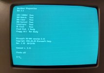
Anyway, that finally fixed the start-up issue. It worked as expected at various power-levels on my rig. So I reassembled everything and installed it again. Finally, the M24 started with a normal POST and "beeeep". Happy days!


I can now see the next steps of the project (restoring my ebay M24): most keyboard keys are unreliable. This will need to be reworked. Also, the color monitor has a contrast issue (and the contrast/brightness controls aren't working at all). Hopefully just an issue with the potentiometers (and not more repairs involving high voltage stuff...

).
Finally, in case anyone else planned to work on an M24 PSU: here's an improved variant of the PSU schematics. I was fed up with the bad quality schematic in the manual - which also has a useless component numbering (not matching the component labels on the PCBs, but using identical numbers for all components of the same type - which is absolutely unhelpful, if you're trying to use the schematic with an actual PCB). I cleaned up the graphics and relabeled everything with the actual component numbers (and values) from my PCBs.
View attachment M24_PSU_Schematic.jpg


