The boards are in the mail, slowly moving from china to the 'glorious motherland.' That gives me some time to assemble all the parts I need for the motherboard. That includes three basic categories: 'chipset' (chip set, so this is where this word comes from, heh), logic ICs, and 'misc.'
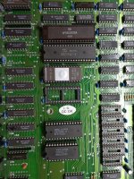
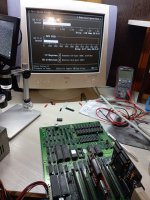
The first group is easy. Lots of 41256, 27C256, 8088, and 8237-8253-8255-8259-8284-8288. The first three are easy, and the 82xx could be sourced from aliexpress and our local online flea market. There were soviet clone ICs of the 82xx line, so I can also use them if needed. I modified my test clone motherboard by installing sockets for all the major chips, so now I can test all of the above right inside a working system. Notice the Soviet КР580ВВ55А instead of D8255A-5. It was tricky to install since it has pins with a 2.5mm step instead of 2.54mm, but nonetheless it works like a charm. Now I have enough ICs for at least one whole new motherboard, so it's OK. Check!
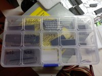
The second is logic, and that is rather bothersome. I think I got everything I need, but I still need to check all of it in an IC tester and make sure that it's all present.
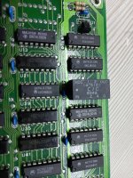
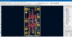
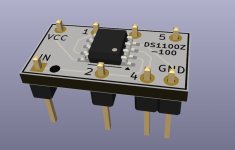
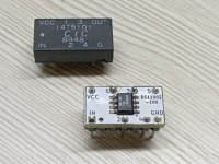
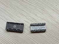
The third is miscellaneous. That includes passives (a surprisingly small amount of elements), crystal, and the most problematic component - delay line. TD1 in schematics, a 100ns 5-output delay line in a DIP-14 package. It's responsible for the generation of CAS and Address select lines. Without it, the machine won't start at all (as expected). I looked EVERYWHERE (where I can buy from of course) - nothing. In desperation, I even bought a couple of dead 286 motherboards with such components so I could salvage them from there, but that is not a way out, plus I HATE to destroy old hardware. But after some additional searching, I found DS1100-100 chip, which is actually a modern version of the one I'm looking for. But it's SOIC-8 package, and I need DIP. After studying the datasheet and making sure that it's compatible, I sketched a tiny adapter board from SOIC to DIP in KiCAD. Today the boards arrived (a friend helped to add my gerbers into his order, so they arrived much earlier than my motherboards), assembled the first prototype and installed it instead of the original. The result is in the photo; everything works
")
So the problem of the delay line can now be considered solved; aliexpress is full of DS1100-100 for less than $2, and since the board outline resembles DIP-14, the boards are tiny and could be ordered very cheaply. Check!
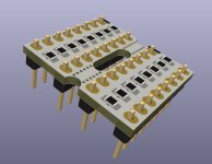
The same approach I want to use for resistor networks. There are five of them on the board, two different types and three different values. I made similar adapter boards so one can just solder 0805 SMD resistors and get a resistor network of a desired value in a DIP package. And it's possible to use original components if required. A win-win situation! They are so far untested, but I don't think there will be problems with them; they are dead simple. Check!
Now I have to finish XTIDE and Adlib board and that's basically it, I am fully ready for assembling and testing.
By the way, I am experimenting with running a Discord server (never done it; could be fun), so if anyone is interested - here is the link:
https://discord.gg/3KUundc9
I think that I have some retro hardware that could be of interest to people, plus a little bit of PCB design knowledge to help others.


.jpg")
 But even in this state it will be more than enough for running the diagnostic rom in my motherboard, as it requires a CGA card to work.


.jpg")
.jpg")

.jpg")


