And i really needed a bootable "floppy" there
")
If i get Sergey's BIOS to work with MartyPC FDC, i will try to put back FDC support, as Sergey suggested.
--
Ok, back to keyboard:
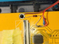
As i figured out earlier, that kbd controller works fine with 3.3V supply. So i googled for a simple way to lower input voltage there - 3V3 Zener diode and 270Ohm resistor (dunno, even if that wrong - it works).
Worked, temp assembly is on photo.
Now it's safe to connect it's signal lines to Pico, and i immediately did that
Data (collected with Pico, connecting controller lines to GPIO pins):
Interrupt line is high on event for ~6130us.
First repeat delay ~620'000us
Next repeat delay ~61'550us
It keeps last pressed key state only, so if 1-2-3 pressed one after one, releasing 1,2 will result in setting third scancode after sending release, but if done backwards (release 3,2) - only releases are reported.
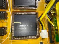
So idea now - put 8 keyboard lines to Pico, cut those together with IRQ line from "BK82C42", implement internal/external device control/switch in Pico and put 8 output lines + IRQ from Pico to "XT-IO" and 8259A.
Waveshare Zero is perfect for the task, it can be easily put inside and has just enough lines.
Coding is not the problem - problem is soldering to those tiny lines.
Can anyone suggest some working method or maybe a correct cable? Everything i tried is too thick.
--
Regarding Turbo - if line is high, turbo is off. So isolating pin 61 will put the Book in always turbo mode, but without any led indication.

")