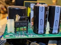
I am working on repairing a dot-matrix printer power supply. Last time it was plugged in, it popped the fuse. I got it opened up today and discovered that the AC-to-minus poles of the bridge rectifier are shorted, so I need to replace it. The markings on the package are "LB-154 68B" and the ac pins are outboard of the +/- pins. Searching suppliers, I find that the parts I have looked at all have AC on the inboard pins and +/- on the outer pins. Can anyone give me clues on how to search for the right pinout?
- VCF South West - June 14 - 16, Davidson-Gundy Alumni Center at University of Texas at Dallas
- VCF West - Aug 2 - 3, Computer History Museum, Mountain View, CA
- VCF Midwest - Sept 7 - 8 2024, Schaumburg, IL
- VCF SoCal - Mid February 2025, Location TBD, Southern CA
- VCF East - April 2025, Infoage Museum, Wall NJ
-
Please review our updated Terms and Rules here
You are using an out of date browser. It may not display this or other websites correctly.
You should upgrade or use an alternative browser.
You should upgrade or use an alternative browser.
Bridge rectifier in a SIP-4 package with AC on the outer pins?
- Thread starter russell--
- Start date
Hugo Holden
Veteran Member
That is interesting. Most SIP bridge rectifiers have the AC on the inner pins, + & - on the outer and on the package there is a taper on the corner that is at the + end.
There are some variants that have the pins staggered instead, like this :
www.farnell.com/datasheets/48711.pdf
But that variant doesn't match what you need.
But it is pretty uncommon to see both AC pins on the outer. Are you sure about the wiring ?
Can you post a photo of the one you are trying to replace ?
What sort of voltages and currents is it expected to handle ?
What you can do though, to deal with this situation, is to use a bridge like a W0-4 and you can easily arrange the AC leads to the outside and the + & - to the middle.
pbirkel@gmail.com
Veteran Member
Great suggestion!What you can do though, to deal with this situation, is to use a bridge like a W0-4 and you can easily arrange the AC leads to the outside and the + & - to the middle.
That is interesting. Most SIP bridge rectifiers have the AC on the inner pins, + & - on the outer and on the package there is a taper on the corner that is at the + end.
There are some variants that have the pins staggered instead, like this :
www.farnell.com/datasheets/48711.pdf
But that variant doesn't match what you need.
But it is pretty uncommon to see both AC pins on the outer. Are you sure about the wiring ?
Can you post a photo of the one you are trying to replace ?
What sort of voltages and currents is it expected to handle ?
What you can do though, to deal with this situation, is to use a bridge like a W0-4 and you can easily arrange the AC leads to the outside and the + & - to the middle.
It turns out, as you can just about make out if you look closely, there is an alternative set of pads on the board for the more common pinout. It is a regular 110V AC input power supply, and there is a 2A fuse upstream of the power supply. I was unsuccessful locating a datasheet for the part, based on the labelling. I salvaged an inline bridge rectifier from a random power supply in my basement, and installed that in the alternative pads, and it didn't catch on fire (yet) when I switched it on. When reading datasheets for vaguely similar form factor bridge rectifiers, I noticed they specify V sub f, as the forward voltage drop, but none of the datasheets I've found say what that drop is measured across. I think I have deduced it is from the negative to the positive terminals, so two diodes worth. The one that failed has an individual diode drop of a little over 0.5V, so I infer that the V sub f would be like 1.05 or 1.10V.