NeXT
Veteran Member
****CLICK HERE FOR PART 5****
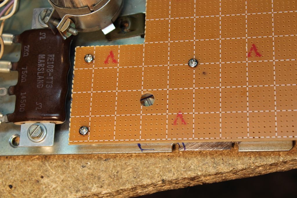
I had to drill a larger hole to reach a screw beneath. It was for the bracket that held the dial and buttons and there was no easy way to install the board with it in place. Instead you could mount the board, slip in the bracket and tighten the screw down through the hole.
>>>IMAGE<<<
I bought two different sizes of standoffs because I did not know exactly how much clearance I would need. After testing the clearances with both I settled on a ¼” gap.
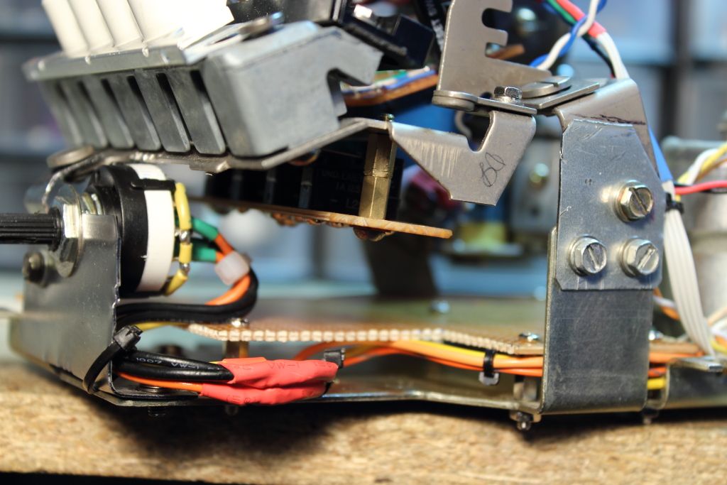
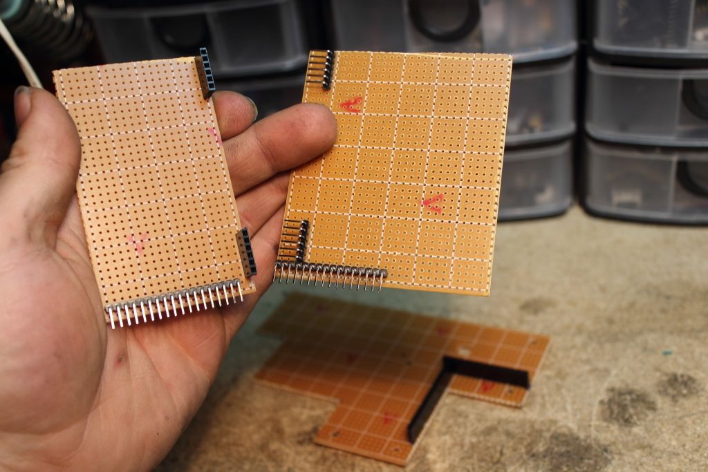
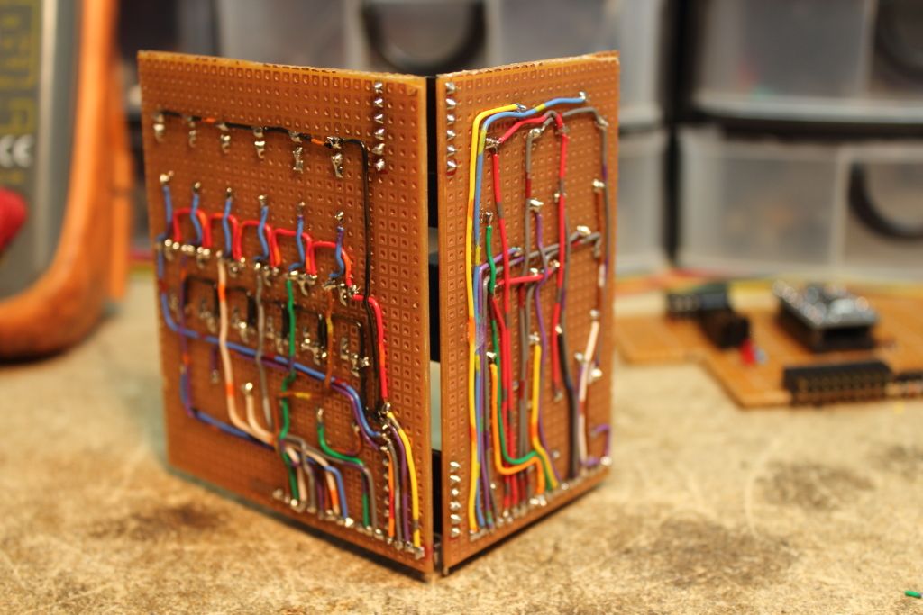
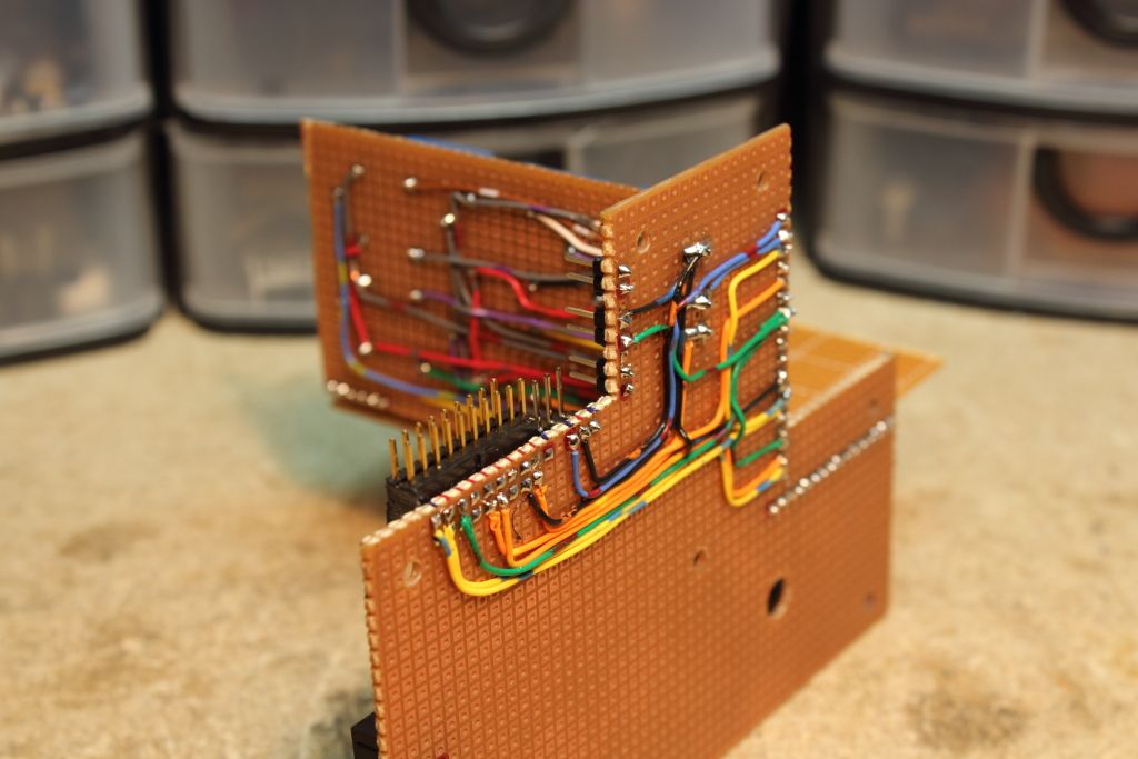
Even with all that perfboard, I expected that I would still be short on space. I had two ways I could approach that. One was to layer the boards as they were but that meant that I might run into clearance issues. The other idea which I did settle on was two vertically mounted boards using single row pin headers both to plug into the main board and two smaller sets to connect them together for stability. I was now able to start laying out where I wanted connectors to be and how everything would fit. After a few test mounts they were soldered down and I was ready to begin the fun part.
>>>IMAGE<<<
>>>IMAGE<<<
>>>IMAGE<<<
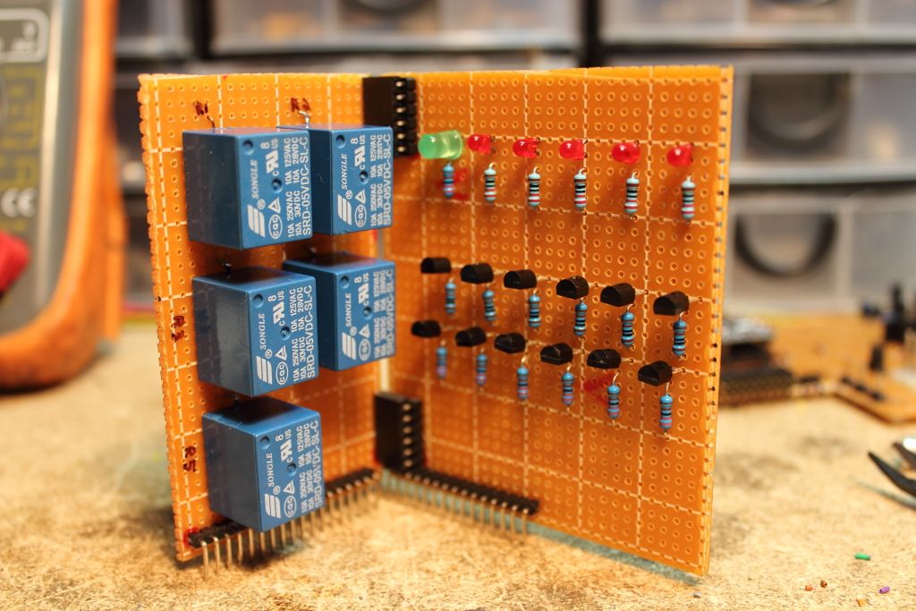
I now had all my point A’s and my point B’s. I had wiring diagrams telling me how everything needed to be connected and I was pretty sure at this point that everything was going to work. The first board I assembled would simply be known as the Relay Board. Five 5v coil relays that would do all the heavy switching I didn’t consider fit for a transistor like the 3904. Every line had its own pin on the bottom edge.
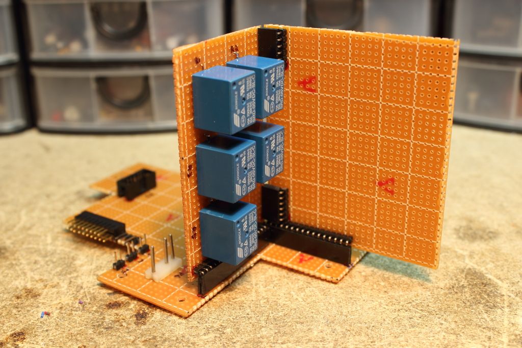
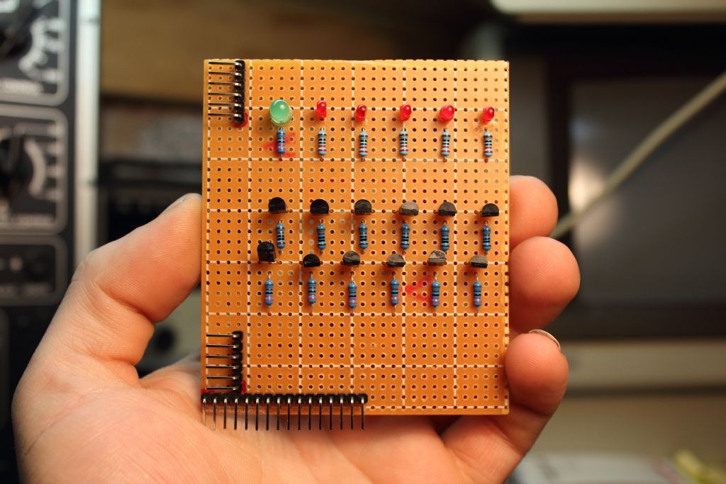
The other board would be called the Transistor Board. It consisted of nothing but standard 2N3904 transistors, a few resistors and a row of LED’s that gave me a remote location to see what the modem was currently displaying. The green LED was used to verify that the modem was in fact on.
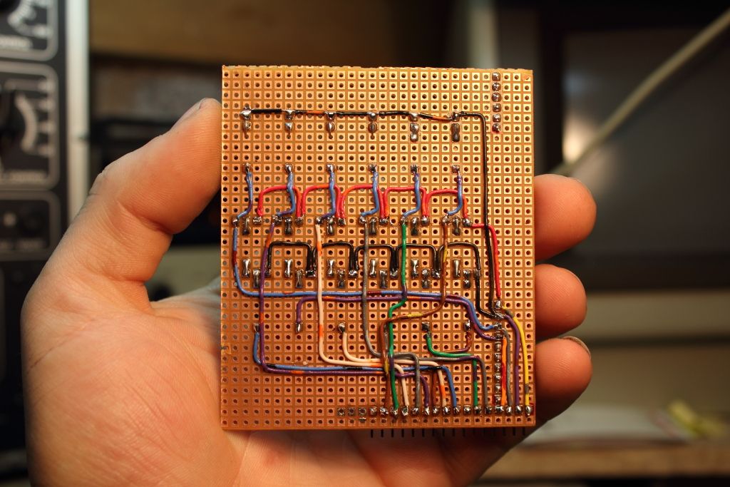
Both boards were again made using perfboard which meant that all lines had to be soldered by hand using copper wire. This is again one of those points where a good idea on layout and multi-color telephone trunk wire can come in really handy.
****CLICK HERE FOR PART 7****
I had to drill a larger hole to reach a screw beneath. It was for the bracket that held the dial and buttons and there was no easy way to install the board with it in place. Instead you could mount the board, slip in the bracket and tighten the screw down through the hole.
>>>IMAGE<<<
I bought two different sizes of standoffs because I did not know exactly how much clearance I would need. After testing the clearances with both I settled on a ¼” gap.
Even with all that perfboard, I expected that I would still be short on space. I had two ways I could approach that. One was to layer the boards as they were but that meant that I might run into clearance issues. The other idea which I did settle on was two vertically mounted boards using single row pin headers both to plug into the main board and two smaller sets to connect them together for stability. I was now able to start laying out where I wanted connectors to be and how everything would fit. After a few test mounts they were soldered down and I was ready to begin the fun part.
>>>IMAGE<<<
>>>IMAGE<<<
>>>IMAGE<<<
I now had all my point A’s and my point B’s. I had wiring diagrams telling me how everything needed to be connected and I was pretty sure at this point that everything was going to work. The first board I assembled would simply be known as the Relay Board. Five 5v coil relays that would do all the heavy switching I didn’t consider fit for a transistor like the 3904. Every line had its own pin on the bottom edge.
The other board would be called the Transistor Board. It consisted of nothing but standard 2N3904 transistors, a few resistors and a row of LED’s that gave me a remote location to see what the modem was currently displaying. The green LED was used to verify that the modem was in fact on.
Both boards were again made using perfboard which meant that all lines had to be soldered by hand using copper wire. This is again one of those points where a good idea on layout and multi-color telephone trunk wire can come in really handy.
****CLICK HERE FOR PART 7****