NeXT
Veteran Member
****CLICK HERE FOR PART 8****
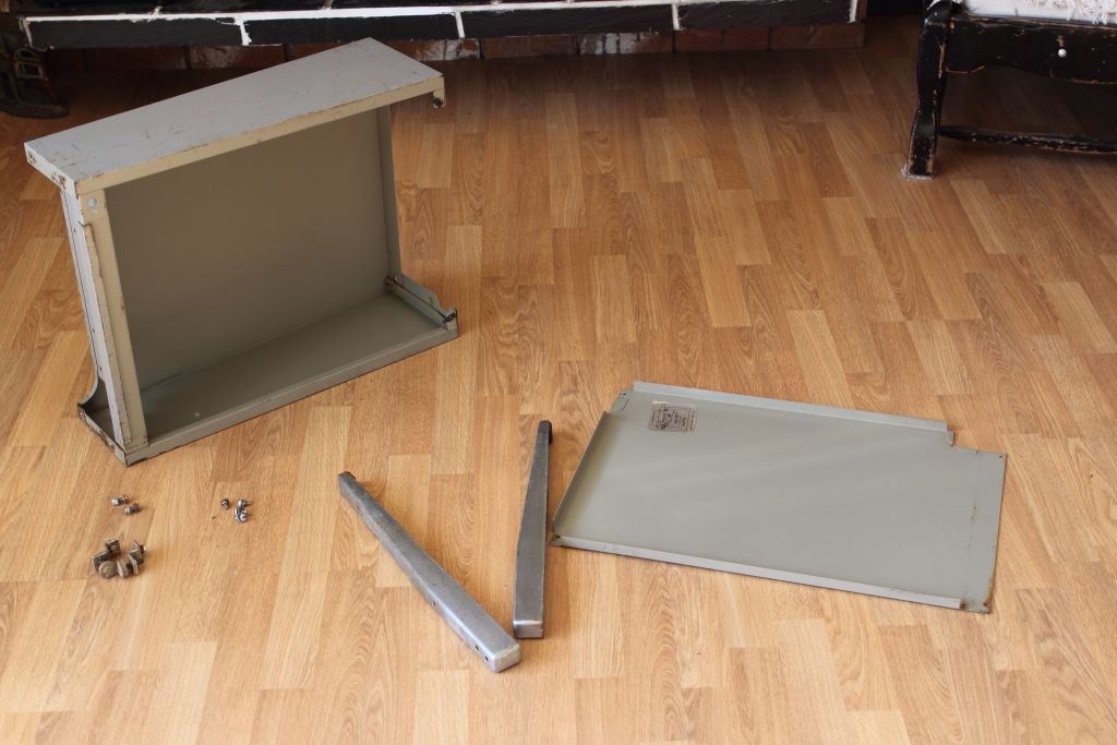
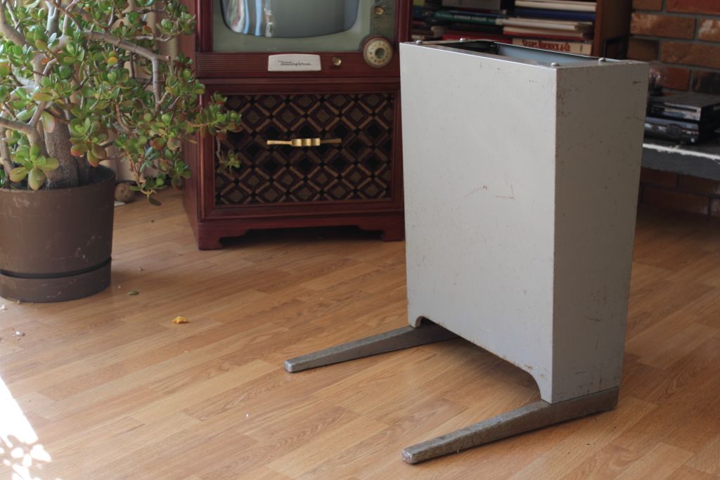
In the meantime a fellow from out east gave me a shout. He knew that my teletype was using a wooden stand I built myself. By chance he had just bought a basketcase model 33 that he was about to trade away for a better one but the new owner didn’t want the stand. A small fee was agreed on and a week later I finally had a proper stand for my teletype. It was grubby and rusty but I’m not complaining and it looked a lot better after it was given a cleaning.
After several more days messing with powering the DTMF adapter externally I was recommended I remove a resistor out of the circuit and feed in power through any point on the 5V rail it used. Suddenly things started working. The emitted tones were distorting but after playing with some resistor values I found that a 100 ohm resistor in series with 5V made everything play nice.
>>VIDEO<<
Now that I was reliably dialing out I then re-added the bell. It is simply wired across the telephone line before the hook switch. A polyester capacitor on one side means that when the phone is in its DC mode the bell does nothing but when the exchange sends the 90v AC to ring the bell the bell will do exactly that. A small modification was then made to the phone relay board I had installed near the beginning of the project. The “anti-tinkle” resistor was also removed as it was no longer needed.
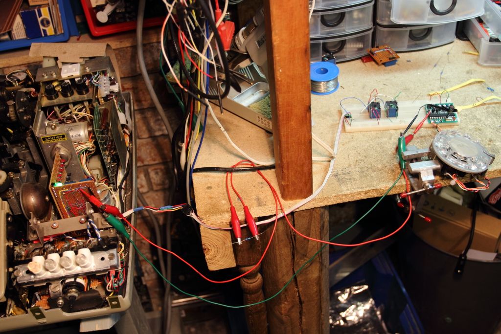
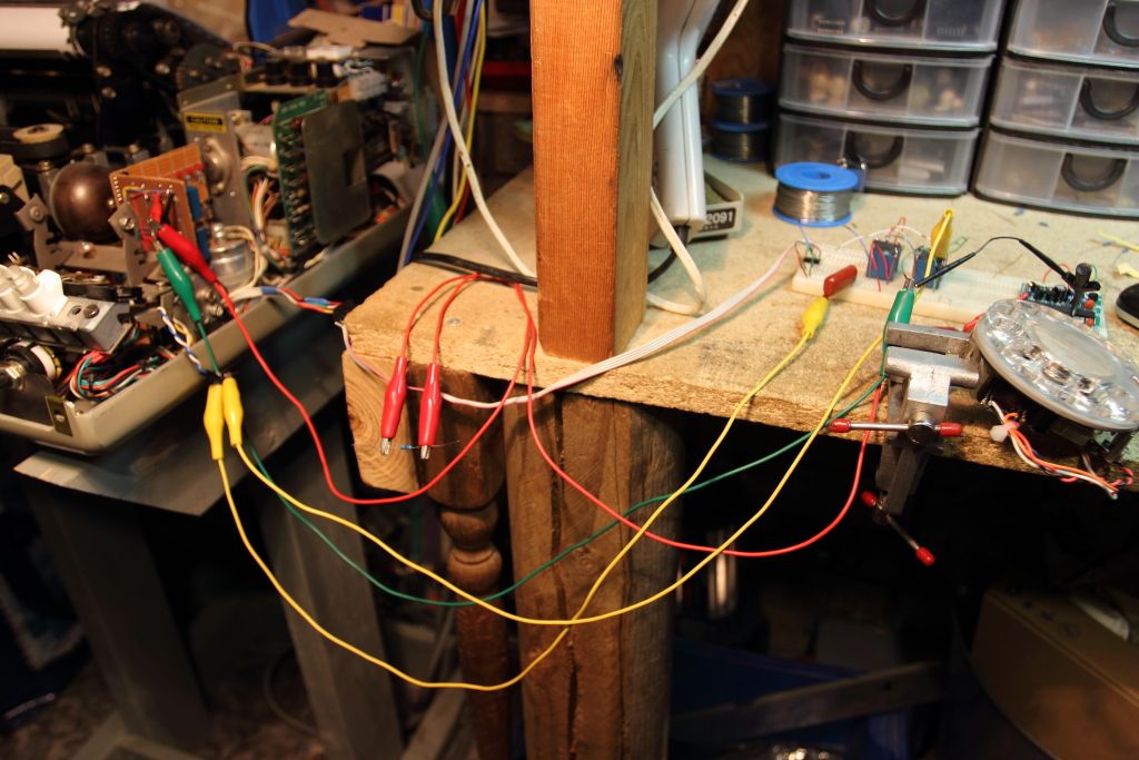
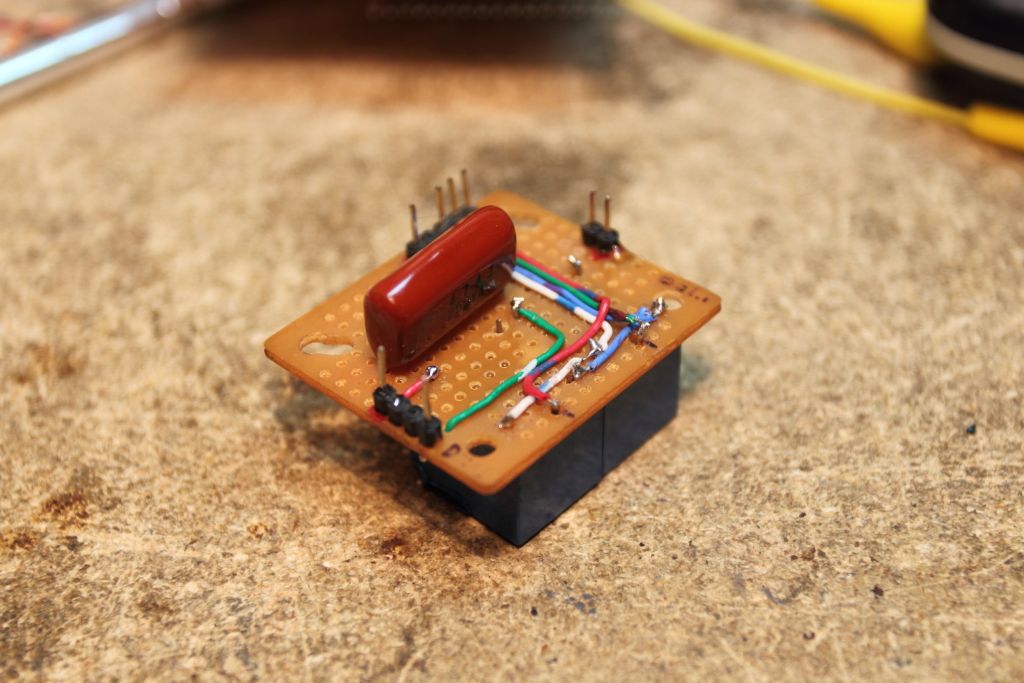
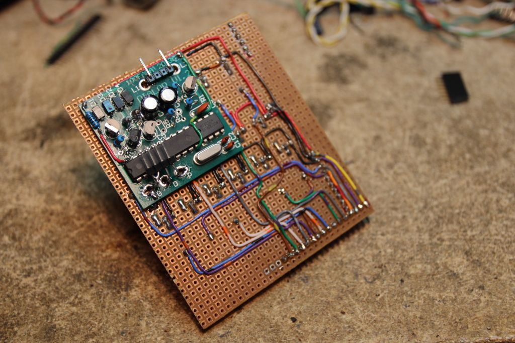
There was no longer any more space on the board for the DTMF adapter and I needed to supply it with 5v from somewhere. After scouting out a location I found the back of the Transistor Board to be very much suitable. Three small holes were drilled through the board and riser pins were soldered in place so that everything was securely fastened. A new lead was made to run from the phone relay board to the adapter and then back out to the rotary dial.
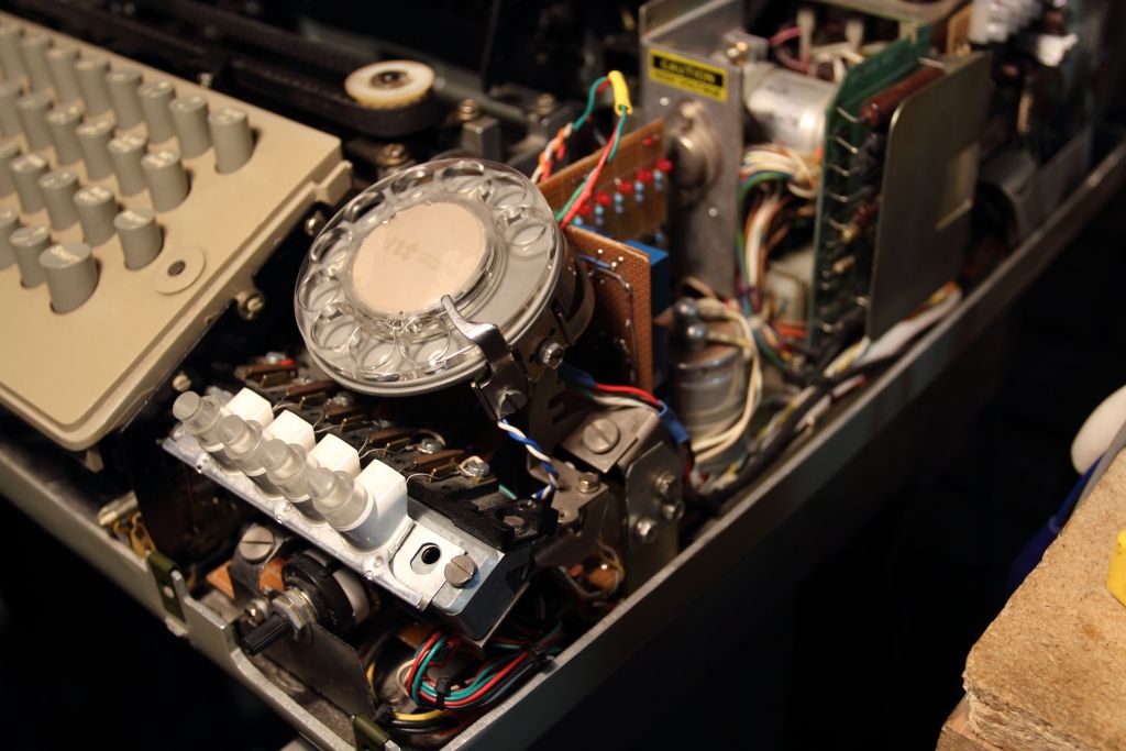
With nothing else left on the list to build I decided to clean one thing up. The CCU was almost completely modular. Because of where I mounted the motor relay there was a loose wire that snaked around the back of the machine to the CCU. I decided to completely relocate the relay to the CCU side of the plug, which delivered power to the motor. Because up to now I had tried to make sure that everything inside could be undone in the future should the need arise this only took five minutes to do.
****CLICK HERE FOR PART 10****
In the meantime a fellow from out east gave me a shout. He knew that my teletype was using a wooden stand I built myself. By chance he had just bought a basketcase model 33 that he was about to trade away for a better one but the new owner didn’t want the stand. A small fee was agreed on and a week later I finally had a proper stand for my teletype. It was grubby and rusty but I’m not complaining and it looked a lot better after it was given a cleaning.
After several more days messing with powering the DTMF adapter externally I was recommended I remove a resistor out of the circuit and feed in power through any point on the 5V rail it used. Suddenly things started working. The emitted tones were distorting but after playing with some resistor values I found that a 100 ohm resistor in series with 5V made everything play nice.
>>VIDEO<<
Now that I was reliably dialing out I then re-added the bell. It is simply wired across the telephone line before the hook switch. A polyester capacitor on one side means that when the phone is in its DC mode the bell does nothing but when the exchange sends the 90v AC to ring the bell the bell will do exactly that. A small modification was then made to the phone relay board I had installed near the beginning of the project. The “anti-tinkle” resistor was also removed as it was no longer needed.
There was no longer any more space on the board for the DTMF adapter and I needed to supply it with 5v from somewhere. After scouting out a location I found the back of the Transistor Board to be very much suitable. Three small holes were drilled through the board and riser pins were soldered in place so that everything was securely fastened. A new lead was made to run from the phone relay board to the adapter and then back out to the rotary dial.
With nothing else left on the list to build I decided to clean one thing up. The CCU was almost completely modular. Because of where I mounted the motor relay there was a loose wire that snaked around the back of the machine to the CCU. I decided to completely relocate the relay to the CCU side of the plug, which delivered power to the motor. Because up to now I had tried to make sure that everything inside could be undone in the future should the need arise this only took five minutes to do.
****CLICK HERE FOR PART 10****