• Please review our updated Terms and Rules here

Building a CRT pip-boy because why not?(Also for school project because why not?)

CompaqSniffer

Experienced Member
Joined
Oct 8, 2024
Messages
95
Location
Charleston SC
I posted a thread earlier about a Sony watchman FD-10A, and got a little off topic.
Long story short, I wanted to use the FD-10A for the screen, but it had some issues and I didn't feel like buying a bunch of parts right now. I got lucky and my professor gave me an old B/W television, and it's a 4.5in screen. There are so many other CRTs I could've used, but this is the one I have and I think it'll work.

If anyone knows of someone who's attempted this before please link me videos, I could use the help. As far as I know no one has done this so I'm in murky water.

- If you have any cool CRT suggestions for this I'll still take them, here's some I know so far:

- Camera viewfinder CRTs( they're about 1in)

- Electrostatic oscilloscope tubes(specifically the 1in ones since they're really short).

- Any Sony watchman really, also any side mounted e gun CRTs.

- a Sony watch cube might work but I can't find them.

All of these tubes have something in common, and that's that they are small, but most importantly short. In order for this to work well, I don't want the CRT to be longer than 4in, with the neck board.

AN example of a unicorn CRT that would do perfectly, would meet every one of these requirements, but we don't live in a perfect world so finding a CRT like this is impossible:

- Any monochrome that's not B/W
- less than 4" long
- 3" wide diagonally
- has a tiny controller board like a viewfinder CRT.

Good luck Internet sleuths because you won't find it, instead let me show you what I have, and tell you where I'm at with this.

I'm currently trying to replicate a Pip-boy 2000 mk.4, because for some reason Bethesda decided to put their best designed pip-boy in their worst designed game, Fallout 76(admittedly I have played a lot of it and I'm ashamed to admit it). Politics aside, this is my favorite model because it actually has two little vacuum tubes under the Geiger counter and the holotape reader is clearly visible on the bottom. This pip-boy is also the largest if you factor in the IRL real model. I've seen many people make pip-boys but they always use an LCD screen. I don't blame them, it's way less of a headache to do so. Here's a 3D-printed (inaccurate) model so we know what we're working with:IMG_20250412_221955_HDR.jpg
Don't let the picture fool you, this thing is massive, just the plastic alone, and this thing feels like a wrist mounted brick. Don't worry, I'm not using this exact model, this is just a reference point (modeling my own is going to be a nightmare though, the central piece took 50 hours to print).
Trust me I'm an engineer(physics major).

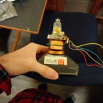
Anyway here's it next to the tube I'm using:
IMG_20250412_222203_HDR.jpg
That tube is 4.5in along the diagonal for scale.
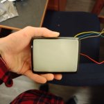
This is it in its original case:
e3fa29e7-9b49-434c-adb1-890db7e148ea.jpg

Here's how big it is in reference to my arm:
IMG_20250406_000156_HDR.jpg

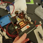
Currently I am working on composite modding this thing, I want to fully reverse engineer the controller board and slim it down. I have some perf board for this, and I have the datasheet for the video chip. I plan on fully removing the tuner, and that should slim it down a little. If anyone knows how to easily drive a B/W TV please let me know, this controller board is single sided, but it's still going to be painful to reverse engineer it without a schematic.
I can post images of both sides of the board if you want me to.

Here's how it's going with the composite mod, I was probing the board in this picture,(yes I know I'm not using a scope that can see the composite signal in all of it's glory) and was looking for a composite signal. What's on the scope in the picture is composite video from my raspberry pi.
IMG_20250411_233031_HDR.jpgIMG_20250411_232921_HDR.jpg

Here's the arm strap I'm using, it's two zebra wrist terminal bracelets. The blue thing is me prototyping a mount that clips onto them:
IMG_20250407_205910_HDR.jpg

Here's the walkman clone I ordered for the "holo-tape" reader. It has a built-in radio so I'm killing two birds with one stone, knocking the radio and the tape drive off of the list:
Screenshot_20250412-222344.png
It says parts only, but that's because the battery bank is slightly corroded, the description says it still plays.

Am I forgetting something? Idk I've been typing this for about an hour on my phone, I'm just going to post it, I'm hungry.
 

Attachments

  • IMG_20250405_235745_HDR.jpg
    IMG_20250405_235745_HDR.jpg
    1.2 MB · Views: 1
  • IMG_20250406_000214_HDR.jpg
    IMG_20250406_000214_HDR.jpg
    879.2 KB · Views: 2
  • IMG_20250406_000210_HDR.jpg
    IMG_20250406_000210_HDR.jpg
    740.9 KB · Views: 2
Oh I know what I forgot, I have plans for the Geiger counter later, going to use an Arduino nano, and an old Soviet pancake tube, this puppy is going to be a trinket alpha detector.

I helped one of my friends modify his counter to take one, and it was an awesome mod.
 
The big problem with the flat screens is that the neck is actually more inconvenient than a regular one. I have a Sony watchman FD-10A and it has a flat screen. It also has geometry issues. I have that exact flat screen on the way because I was thinking that maybe I could use the controller board to drive a regular CRT, it's controller board is really small.
 
The flat CRT PCB would have a very specific deflection output I would imagine that would not work well with other tubes.

They do have some distortion, but it wasn't so bad that it was unusable when I pumped graphics into mine.
 
The flat CRT PCB would have a very specific deflection output I would imagine that would not work well with other tubes.

They do have some distortion, but it wasn't so bad that it was unusable when I pumped graphics into mine.
I thought about that as well, the deflection is different for the flat screens, but I also got to thinking that maybe the flat screens are easier to reverse engineer, and I might could modify it to have regular deflection. As it stands, I think if I hook up the wires straight to my CRT, the image probably would only fill up the bottom half of the screen, and it would be "smushed." I could be being hopeful, but I don't really have another option besides existing CRT controller boards. I don't have the knowledge to build a controller board myself with what I have.
 
Also here's the schematic for the IC inside the B/W CRT I'm using:
IMG_20250331_152107_HDR.jpgIMG_20250412_222203_HDR.jpg

Currently, I tried lifting pin 5 to input a composite signal, but that just gave me a horizontal line.
Pin 5 is the video output, so if I cut it and inject my composite into the board it should display an image, but it doesn't.
 

Attachments

The alternative is plasma displays.

Plasma displays - even complex ones - did exist quite early on. I always thought the pip-boy was a plasma - not a CRT.

They were first invented in 1964 and their complexity was only limited by memory developments, as plasma display incorporate memory and display elements together ( like a CRT with memory ) so they got more advanced as memory got better.

They also have the same kind of glow as CRTs.

OTOH, finding a 4" plasma display might be even harder than finding a good small CRT.
If you look at my history on this website I am all to familiar with plasma displays, they are painful to get working, and while I do agree it would look cool, I would also agree finding a 4" (working) plasma display would be impossible. Plus you only have one color being red(neon gas). Also they are incredibly expensive NOS. As a quick shill, I am currently working on a guide for repairing Compaq Portable III plasma screens, but it's not for the faint of heart. It's still in progress and I am also incredibly busy with college getting close to finals.
Due to the iconic shape of a CRT, and it's similar appearance in game I think the pip-boy actually uses a CRT.
 
Um, CRTs are inherently memory, in fact the first random access memory. The first electronic stored program computer, the 1948 Manchester Baby, was actually designed as a testbed for CRT memory.
It's always Interesting to learn about Early computers I did not know that. Seems like an overly complicated and unreliable way to do memory. Nonetheless very fascinating, seems like something an actual mad scientist with an infinite budget would construct. I wonder why they went with a CRT over any other vacuum tube, though I'm not to familiar if you could make fast memory with regular tubes. I'm just now learning about vacuum tubes really.
 
The big problem with the flat screens is that the neck is actually more inconvenient than a regular one. I have a Sony watchman FD-10A and it has a flat screen. It also has geometry issues. I have that exact flat screen on the way because I was thinking that maybe I could use the controller board to drive a regular CRT, it's controller board is really small.

The drive between a traditional CRT vs a side shot CRT is considerably different, it won't work. Even if it did, the geometry on a normal CRT is going to look very strange and warped. There's a video floating somewhere around Youtube showing a scope trace of the deflection on a side shot CRT and it almost looks like a shark fin, which it has to since the screen surface is not only at a sharp angle to the beam, but it's curved.
 
Um, CRTs are inherently memory, in fact the first random access memory. The first electronic stored program computer, the 1948 Manchester Baby, was actually designed as a testbed for CRT memory.

“Inherently”? In the case of the Williams Tube, only if you have the pickup plate covering the front of it, meaning you can’t look at it and have it actually work at the same time. (The system relies on the static charge that’s created when the electron beam scans an area, which fades fairly rapidly. Thus the tube is essentially a dynamic RAM, in which the contents of each cell need to be regularly read out via the detection grids and looped back around to be rewritten.)

Anyway…

They were first invented in 1964 and their complexity was only limited by memory developments, as plasma display incorporate memory and display elements together ( like a CRT with memory ) so they got more advanced as memory got better.

I’m pretty sure you’re misunderstanding what “memory” means on the Plato display. It doesn’t literally have accessible memory elements in it; the screen relies on a hysteresis effect accomplished by mixing a strategic amount of nitrogen into the neon in the display. This miracle of chemistry allowed the *lit* elements of the display to stay lit by applying a hold voltage to every element of the display, but to switch a dark pixel on required an extra jolt to get it to glow. This lets the screen act like an etch-a-sketch; data written will persist as long as you want, passively, without needing an active video buffer.

The downside is you can’t *un-light* individual pixels once lit. The Plato handled this by dividing the screen into zones that could be blanked (by dropping the hold voltage) and rewritten separately without having to redraw the whole thing.

The best analogy to the Plato screen is probably the storage CRTs that they used on those Tektronix graphics terminals in the ‘70’s; they also relied on a combination of hysteresis in the tube phosphor, use of a “flood” beam to keep lit parts lit, and zoned updates on some of the fancier ones.
 
Seems like an overly complicated and unreliable way to do memory.
Oh, wait until you find out about mercury delay lines.

But actually it's not that complex (basically a TV with a sensor in front of it), and could be made reliable enough that it was used in systems such as telephone exchanges.

I wonder why they went with a CRT over any other vacuum tube....
Because you could put lots of glowy spots on a single CRT, and they would stay glowing for long enough (on the kinds of timescales that computers use) that you could easily refresh them before they went away.

“Inherently”? In the case of the Williams Tube, only if you have the pickup plate covering the front of it...
Yes, inherently. Even without the pickup plate, a CRT is a dynamic storage device in that you can set memory areas and it remembers their values for awhile. Sure, the memory fades, but so does that of DRAM, which most people still consider to be inherently a memory device independent of whether it's used properly or not. (I.e., someone wouldn't say that a 4116 is no longer a DRAM chip because someone plugged it into a machine without a refresh circuit.)

...meaning you can’t look at it and have it actually work at the same time.
I'm not sure I see the issue there. You can't look at the workings in a DRAM chip while you're using it, either, and nobody really seems to care.

There's no particular reason that a CRT has to be something that humans look at.
 
There's no particular reason that a CRT has to be something that humans look at.

Really? The point of the discussion here is a specifically a display device which doesn't require refresh. Williams tubes are memory devices, full stop, that happen to use CRTs. I suppose in principle you could build a sensor grid that has holes large enough to allow some light to shine through... although there were also instances where Williams tubes were paired with a visible CRT that replicated the state of the memory tube; you could use this to give you a (low resolution) "graphics display" if grids of loosely spaced dots really float your boat, but let's be real here, Williams Tubes are *not* relevant to the topic at hand, even if they are cool.

FWIW, those Tektronix storage tube terminals from the 1970's I mentioned *were* able to read out the contents of the screen by using the (nearly transparent) electrodes that are embedded in the screen face that work with the flood beam to provide the "sustain" function and send it to a printer. Per a 4051 tech manual, page 6-37:

Hard copy information is read from the face of the crt by means of a pulsed writing beam of low
intensity. Whenever the writing beam touches the target or storage backplate (screen) of the
crt, there is an increase in current. This current is sensed as a differential voltage on the output
of a pulse transformer and amplified by the hard copy crt readout amplifier circuitry. Target
signal information is then placed on the TARSIG signal line. Bright display areas generate
more target current than areas that are not written; therefore the crt readout amplifiers can
discriminate between bright and dark areas of the display.

But again, this is a function of a *very specialized* type of CRT. I mean:

Yes, inherently. Even without the pickup plate, a CRT is a dynamic storage device in that you can set memory areas and it remembers their values for awhile.

If we're going to play this game then *any* kind of electrical device is a "memory". If I flick a light bulb on and off the filament is going to stay warm for a while, do we want to call that a "memory device"(*)? Sure, you get a fading glow from the phosphor and a bit of static electrical charge on the glass that persists for a while after the electron beam goes by, that doesn't make it a "memory" unless you have some capability of reading or sustaining it, which you *don't* get without glomming additional technology onto the tube.

(* I mean, theoretically, if you put some kind of temperature sensor next to the bulb and calibrate it very carefully to the ambient temperature of the room and know very precisely the rate at which the filament cools off we could make this work by periodically flickering power to the bulb to keep the "1's" in the "warm" range... but again, the light bulb *itself* isn't a "memory". Now if we make that light bulb a neon bulb with a reliably tuned hysteresis effect so it'll come on when addressed and stay on until specifically cycled we *could* call the bulb itself a "memory", which is what's happening in those old plasma displays. But it's only a "memory" for the humans looking at it, you'd need to add some kind of sense circuitry to be able to allow the computer to reference what it wrote.)
 
I actually have been theorizing how the plasma screens worked, and I know how the topic of cold plasma works. The idea is to get two electrodes in a tube, and apply a large potential difference between them, aka high voltage on one end. When the pressure of the air, and the voltage is just right, you'll form a cold plasma. For pressure, you want it close to a vacuum, but not all the way (you can't excite electrons if there are no atoms). The amount of voltage you apply is dependent on the voltage, and there's a "low" voltage sweet spot where the pressure is at the best spot for the lowest possible voltage you have to apply.

Neon gas is used in gas plasma screens, and I'm pretty sure the screen is just one large gas container with thousands of tiny electrodes, as making individual vacuum bulbs that tiny and putting them into the screen sounds like a chore.

Since I have experience working on plasma screens, there are vertical and horizontal chips that when combined, most likely can individually access each pair of electrodes, exciting only the atoms between that small area. This is how I'm guessing how they work without googling. Also I forgot to mention that the gas is already in an excited state, as it requires more voltage to get the excitement started than sustaining it. The higher the voltage while the plasma is visible, will increase the brightness. Anyone feel free to correct me, I'm still an undergrad in physics.
 
I actually have been theorizing how the plasma screens worked,

Here's a good article about the evolution of gas plasma screens. The technology evolved a lot over the years and devices like the Plato screen differ is some ways from more modern screens capable of things like, well, grayscale.
Neon gas is used in gas plasma screens, and I'm pretty sure the screen is just one large gas container with thousands of tiny electrodes, as making individual vacuum bulbs that tiny and putting them into the screen sounds like a chore.

Obviously they're not literally composed of many thousands of independent little bulbs, and most monochrome screens do use an "open cell" design. Color screens, however, need to have the different phosphor colors subdivided by little glass ridges... in other words, they're pretty nightmarishly complex despite not literally being a bunch of tiny bulbs. FWIW, as the article explains, plasma screens don't *have* to be red. Color screens use a xenon plasma that emits ultraviolet light, which in turn stimulates a phosphor. So strictly speaking you can make a plasma screen whatever color you want.

Anyway. As also is made clear by the article, those 1960's plasma displays were *horrendous* power hogs. I don't think you'd be carrying one around on your wrist unless you had a very long extension cord for it. Frankly I think the only real-world tech that even remotely makes sense in the "Pip Boy" would be electroluminescent. Dot matrix EL displays were demonstrated as early as 1965, and non-dot-matrix but pretty complex implementations of it were used for things like the Apollo guidance computer. And notably many of these early EL displays are roughly the same color green as the pip boy display.
 
Back
Top