• Please review our updated Terms and Rules here

Building a PDP-11 from scratch

It's not what was asked but there is a Gitlab link:

"attempt to build a motherboard (how many layers this monster will be ? no idea)" just kind of noted in passing at the end of the list...

All the logic boards are the smallest part of the problem and the technologically easiest part.

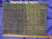
The backplane in the 11/70 was a two piece wire-wrapped monstrosity that was the single largest cost part of the system.
In fact it was the manufacturing cost of the backplane (as both PCB technology and wirewrap technology, using both single ended and diffpair wire wrapping)
that was a significant factor in the discontinuance of the 11/70 and its follow-on 11/74.

Cloning the existing 11/70 boards 1:1 does nothing to improve the technology needed to build the backplane,
which I think has been completely misunderstood and woefully underestimated as to the complexity.

You can easily get away with just four layer (2 signal, 2 planes) for all the boards, maybe some can be done as just 2 layer boards.
But the backplane connectivity now implemented by random wire wrap will require, who knows, maybe 18 or 24 layers to get it all in in etch.
And these would be very large (meaning very expensive PCBs).
 
Last edited:
Honest question: I know nothing about the topic, but it seems to me that amateurs made two layers PCBs for Qbus, what makes a PCB for Unibus so special?
After all many signals are just connected to the same pins on every connector and there is no chips, what I am failing to see?
 
@jplr:
Backplane implemented by random wire wrap because private connections between the various boards forming the cpu, not just a bus.

Why not a hybrid backplane: PCB + wrapping?
 
Honest question: I know nothing about the topic, but it seems to me that amateurs made two layers PCBs for Qbus, what makes a PCB for Unibus so special?
After all many signals are just connected to the same pins on every connector and there is no chips, what I am failing to see?
The CPU isn't Unibus. The CPU consists several dozen boards that are uniquely cross-wired in the unique backplane. Timing (and noise) is critical most everywhere ...
 
The CPU isn't Unibus. The CPU consists several dozen boards that are uniquely cross-wired in the unique backplane. Timing (and noise) is critical most everywhere ...
In the attached photo the CPU is the left half. To the right are 4 MASSBUS controllers, then finally a short Unibus segment on the far right.
 

Attachments

  • 112418849528 Back.jpg
    112418849528 Back.jpg
    667.7 KB · Views: 36
You can easily get away with just four layer (2 signal, 2 planes) for all the boards, maybe some can be done as just 2 layer boards.
But the backplane connectivity now implemented by random wire wrap will require, who knows, maybe 18 or 24 layers to get it all in in etch.
And these would be very large (meaning very expensive PCBs).
where's the fun if there is not a difficulty somewhere :cool:
 
While on this topic, does anyone here have schematics for the KDA50 controller (M7164)?
The print set would be MP-01423.

I know I had a hard-copy years ago, but I must have disposed of it...

I still have an M7164 module, so it makes me think of project ideas... [Danger, Will Robinson!]

Thanks,
Pete
Hi,
I have a few questions about the M7164:
- This is a QBUS card isn't?
- Half of the microcode deals with the QBUS control so only the other half would have to be hacked?
- It seems there are resident diagnostics, is it possible to create a new diagnostic?


Last edited:
Hi,
I have a few questions about the M7164:
- This is a QBUS card isn't?
- Half of the microcode deals with the QBUS control so only the other half would have to be hacked?
- It seems there are resident diagnostics, is it possible to create a new diagnostic?
Yes, Qbus. It's a 2-board set -- the M7164 has the Qbus signals; the M7165 only gets power from the bus.
Yes, there is one set of ROMs, but two code "images" in there. The two threads share the same ALU, but have separate sequencers that are active on opposite clock cycles.
Yes, the code includes diags that run on power-up. They drive 4 LEDs, and if there is a fault the code hangs with the current LED status.

If I can get my hands on the M7164 schematic again, my thought is to hand-assemble some very simple code to make it do "something"...

Pete
 
Thanks Pete,
Do you need to have a full M7164 schematic to do simple code to make it do "something"
I guess most 2901-based schematics will follow AMD's application notes, so isn't enough to trace?
- paths between the ROM and the sequencer 12bits (for state sequencing and branching)
- paths between the ROM and the AMD2901s 16bits? (for doing calculations)
- paths between the ROM and on board circuitry 16bits? (not sequencer, not AMD2901s)
So less than 50 paths.

Even if KDA50 is for QBUS and KDB50 for VaxBI, their hardware design and microcode should share some features, so it may perhaps help to reverse engineer the KDA50?
Both use two registers to interface with the host, both have the same interface to disk.
So KDA50 schematics are probably something like this?
1714807351802.png
 
Another question, what is the difference between the M7161 and the M7164?
Is it only that M7161 is for Unibus?
There are schematics for the M7161 and it looks it has 4 2901, CROM, etc.
 
Thanks Pete,
Do you need to have a full M7164 schematic to do simple code to make it do "something"

Even if KDA50 is for QBUS and KDB50 for VaxBI, their hardware design and microcode should share some features, so it may perhaps help to reverse engineer the KDA50?
Both use two registers to interface with the host, both have the same interface to disk.
Yes, you're right. It is certainly possible. And the easier comparison is the UDA50 (M7161), rather than the KDB50. The microcode word format is almost identical. The M7164 designer told me that the M7161 was the basis for the design - the main changes were Unibus-->Qbus, and to make it fit on a quad board by using PALs and such.

So yes, I *could* move forward with the information I have. But if I could get the M7164 schematic, then I could avoid any "tracing and probing"... I always have a list of "projects" to work on, so this one moves higher on the list if I get a schematic. :)

BTW, the KDB50 is essentially a KDA50, but with the bus changed from the Qbus to BI.

Pete
 
Just discovered that bitsavers has a KDB50 microcode listing:
The first page shows that it came from Matt Tedone in 1988 -- I remember Matt.
It has 'conditionals' for UDA, KDA, and KDB! And other good info. So that means I should be able to figure out almost everything ...

Pete
 
Back
Top