It could very well be causing a problem.
Some technical information is at [
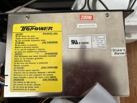
here]. At the flick on the power switch, POWER GOOD is at a TTL LOW level, holding the motherboard, which includes the CPU, in a reset state.
Later, the PSU takes POWER GOOD to HIGH, releasing the reset. The CPU needs that delay (needs to be held in a reset state for a minimum period) - see note 1 at the bottom of aforementioned web page.
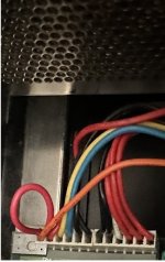
Your P8-1 to P8-2 connection would mean that the CPU is not being reset. Maybe the POWER GOOD output failed on the PSU, and the P8-1 to P8-2 connection was a bad repair attempt.
No. For the IBM 5170, the situation is illustrated at [
here]. Via pin P17 on the motherboard's keyboard controller chip, the power-on self test (POST) in the IBM motherboard BIOS will see that the switch is in the ON position, and as a result, the POST will display, "
302-System Unit Keylock is Locked".
There is no international standard.