• Please review our updated Terms and Rules here

Cassette interface issue: can't load

Good to know it's a cassette thing. I thought it was actual data being transmitted, I'm not very familiar with the Kansas city standard format.

--Christoffer

As audio recorders can only really deal with audio, cassette interfaces typically output either a single tone and silence to represent logic 1 and logic 0 respectively, or long and short bursts of a single tone with long and short representing one logic state or the other, or a continuous stream of two tones - a high tone to represent one logic state and a low tone to represent the other logic state. Not sure which of those schemes your unit will use. The lead-in tone doesn't normally contain significant data, it's just there to give the recording circuit something to measure and adjust itself to before the real data starts flowing.

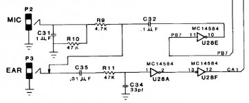
Incidentally, I don't see your image / schematic for the interface anywhere in your previous posts, or is that just me? I would have been interested to see it.
 
Jeez, I forgot to post that. It's attached to this message.
The interface is standard Kansas City - 300 baud, AFSK, " A '0' bit is represented as four cycles of a 1200 Hz sine wave, and a '1' bit as eight cycles of 2400 Hz. " - As I understood from the Wiki article.cass.jpg
PB7 and CA1 are the respective pins on a 6821 PIA
 
Something's wrong with that circuit diagram. If C31 is 1uf it will kill any mic audio. Or is that the purpose of it?
 
You're right. That seems strange, but it doesn't kill the audio. I can record audio off of it just fine. I just ohmed out the connections around it, to check if it was a schematic error, it could've been connected to the switch, opening when the socket is plugged.
 
First thing to notice is the ratio of R9 to R10, which together form a drastic stepdown attenuator to reduce the outgoing signal from the original 0V-5V level on the output of U28E to the very small signal level expected by the microphone input on a cassette recorder. I think the purpose of C31 is to put round corners on what would otherwise be a pretty vicious looking waveform, to make it more audio-like, ie, make it a a pseudo-sinewave.

That loopback through the socket switch is certainly fascinating, why would the unit ever want to be able to listen to its own live output? Unless there's a 'cassette interface loopback test' included in the firmware.

I'm not sure what you have in the way of test gear. A scope? A logic probe? You need to see or hear what is happening on CA1 of the 6821 when the tape is playing into the cassette input. If there's nothing there, look on the output and input of of U28F, if nothing there, look on the output and input of U28A, if nothing there, perhaps C34 is short-circuit or C35 or R11 open-circuit or broken / unsoldered.

If you don't even see a signal on the input end of C35 then I would suspect the input socket is faulty, or that some previous owner had wired / rewired it wrongly... or, some problem with the combination of leads being used (a mono plug plugged into the headphone output of a stereo player would short one channel to ground, possibly even causing the player's amplifier to disable both channel outputs due to the perceived 'speaker fault'.
 
Last edited:
The monitor has a "verify" for tape, but I don't know. - You're right, I should see where the signal vanishes, if it does. I have most test gear needed: Logic puler/probe, DMM, FETVOM, logic analyzer, oscilloscope, so it's just a matter of dragging it all out!

--Christoffer
 
'Verify' in this context normally means, 'listen to what's coming in off the tape but don't transfer it into memory: Just compare it with what is in the memory now and give a pass / fail result'.

The way you would normally use it is:

1) Spend hundreds of hours developing your code, most likely directly in HEX
2) Save it to a tape
3) While your program is still in memory, use the VERIFY feature to read back what you just saved on the tape and compare it with what is in the system memory. If the verification succeeds, i.e, they match, you know the recording is good and you can safely switch off the machine, knowing that you will be able to reload your code. If it fails, you save the code again, maybe onto a different tape, and verify again.
 
That makes sense, but does not explain the loopback switch. Aww.

I think that it's very likely that there was something sketchy in my connectors. They were reused, really crap phenolic based ones. On top of being an extension on the previous owners cassette connections. I think I'll look for the original connector style, install those and then try again, and then trace the signal back through to the PIA.

--Christoffer
 
Back
Top