• Please review our updated Terms and Rules here

Commodore 1084S-D1 - right raster problem

demonlg

Veteran Member
Joined
May 22, 2016
Messages
521
Location
Italy
Hello again to all,

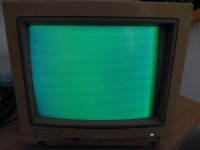
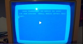
another 1084S, this time model D1 (Daewoo chassis).

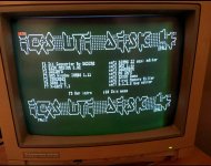
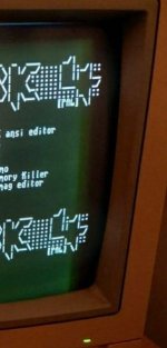
This monitor was turned off for several years and stored in a very humid cellar in Germany. I bought it for 50 euros. When it arrived I cleaned the inside thoroughly, removing dust and dirt and all the electrolytic capacitors were replaced. The monitor works very well and can be seen very well with a signal coming from the C64, but with an AMIGA in RGB, or without any input signal, the right part of the raster seems narrowed by about 1.5 cm, but it is strange that with AMIGA, despite being narrow, the image is still displayed completely, even with the C64 screen in the photo you can see it very well. It seems that this is only noticeable with very dark images. What do you think could this depend on? Voltages or some other component blown?

Emanuele
 

Attachments

  • right band problem2.jpg
    right band problem2.jpg
    74.9 KB · Views: 8
  • right band problem3-c64-LC.jpg
    right band problem3-c64-LC.jpg
    51 KB · Views: 8
  • right band problem-amigaRGB.jpg
    right band problem-amigaRGB.jpg
    119.6 KB · Views: 9
When it arrived I cleaned the inside thoroughly, removing dust and dirt and all the electrolytic capacitors were replaced.
Is there a reason why you replaced them? Did it have the same fault before?
What did you replace the S-correction capacitor with, if it was an electrolytic one?
 
When you encounter a problem like this, the first question you need to ask yourself is:

Is the problem in the scanning raster, or is it in the picture content ?

The two issues are quite unique.

The scanning raster is created by the horizontal and vertical deflection system. This scans the electron beam over the CRT's face. Therefore, picture information cannot be presented outside the confines of the raster scan.

Attaching part of one of your photos, where the right sided defect is, there is nothing wrong with the raster scan, because the picture information is being presented in the normal way on the R side.

But, if you look, you will see in the background, that the average CRT beam intensity fell away on the right hand side, darkening the background.

It appears, primarily, that the fault resides in the horizontal blanking.

What should be happening is that the beam current of the CRT (brightness) should not be altered by the H blanking pulse, until the raster scan is at the extreme right, at the moment it finishes. Then the beam should be blanked for horizontal flyback only at that point until the beam reaches the left hand side.

Your fault suggests that the beam is at least partly blanked (diminished in intensity) prior to the end of the raster scan on the R side.

Therefore, we are looking at an issue of the H blanking pulse not being correct, not a defective raster scan.

One other thing that corroborates this:, The energy stored in the magnetic field of the yoke and flyback transformer, at the very end of the raster scan, on the right, is entirely responsible for the magnitude of the H scan current on the left, because it is a result of reversal of the magnetic field, after flyback. If the raster scan itself, fell short on the R side, it would also be the equivalent amount shorter on the left, which it is not.

As @powerlot was wondering, why was the set re-capped ? and also about the S correction cap. These are very special parts and sometimes people put in inappropriate capacitors.

In general, VDU's should not be globally re-capped and if they are, they should be tested between each capacitor replacement, to ensure that some unexpected fault is not introduced. Unfortunately, there are too many you tube videos out there suggesting global recaps to the unwary, done by people who were still in nappies when the video Engineers designed the VDU's.
 

Attachments

  • RAST.jpg
    RAST.jpg
    34.9 KB · Views: 6
Last edited:
Hello to all,

yes i have recapped board, only most bigger caps and not all, because i found oxid provocated from umidity on top of capacitors and bottom the leakage have damaged any wires.

Previously i have turned on monitor and the problem are the same.

Please question, what is the S correction cap on 1084S-D1 ? Because i check if the cap are new or not.

Emanuel
 
The S correction cap is the special one that is in series with the H yoke's scan coils. Its purpose is to create a low frequency sinusoidal variation in the scanning current of the H yoke coils, to allow for the fact that the sensitivity of the deflection yoke, in terms of how much current results in how much beam deflection, is greater for higher angles angle of deflection. Without this cap, the scan linearity would be compressed in the central area of the screen and expanded on either side.

I don't think this cap is likely the cause if your problem.

Generally in VDU's, a sample is taken of the H flyback pulse, often from the collector circuit of the horizontal output transistor, or an auxiliary winding on the flyback transformer, this is used to blank the CRT beam, when it travels, during flyback, from the R side to the left side of the scanning raster. This is the signal that needs investigating.

I cannot be of much help without the schematic of the VDU.
 
Ok, yes the schematics of this model is here
 

Attachments

  • Schematics only 1084sd1.jpg
    Schematics only 1084sd1.jpg
    402.7 KB · Views: 8
The H blanking in this set is controlled by the sandcastle pulse, I think introduced at pin 10 of the TDA3507, that needs to be checked on the scope.
 
Back
Top