• Please review our updated Terms and Rules here

Commodore 4032-12 dead screen

Reading through this, I have a chip with a 6545. I also have a J7 connector. With a voltmeter, I got these values.
7 - .02
5 - .32
4 - .02
3 - 5.10
2 - .02
1 - .53

OK, the Horizontal Drive (pin 5) is fine. And Video data (pin 1) is active with lots of data probably indicating a garbage screen possibly due to a problem with the Video RAMs. However Vertical Drive (pin 3) seems stuck high which would cause the blank screen. Lets look into that.

Put the voltmeter on the CRTC pin 40 (UB13-40) VSYNC. If that reads about 0.7 volts, we may be lucky and the 6545 may be OK and the XOR gate at UC2 (7486) may be bad. See schematic. Do you have a logic probe?
 
I'd be happy to repair it for you, as well as others here. But, the cost of shipping wouldn't be worth it, IMHO.

PETs are easy and fun to fix. I'm sure you can do it with the great help you can get here, if you're not in a hurry.

Thank you for the kind offer. If I was to ship the board to you, could you take a look? PM me if that's something you are okay with doing and we can work something out.
 
I'm confused. Ok, I assume UB13 is the 6545 chip? I'm not sure where pin 1 is. The chip has a center notch on one side, but I don't know if pin 1 is to the left or right of the notch?

Looking at the schematic, the pin numbers seem totally jumbled. I thought pin numbers traveled counter clockwise, but that's not what I see in the schematic?

I don't have a logic probe.
 
I'm confused. Ok, I assume UB13 is the 6545 chip? I'm not sure where pin 1 is. The chip has a center notch on one side, but I don't know if pin 1 is to the left or right of the notch?

Looking at the schematic, the pin numbers seem totally jumbled. I thought pin numbers traveled counter clockwise, but that's not what I see in the schematic?

Schematics do not usually follow physical layout. Pin1 is to the left of the notch. Pins count down to 20 and around to 21 and back up to 40. So pin 40 is directly across from pin 1.
 
Ok, so what great ideas have the experts come up with to try, to get this thing going again?

I do not want you to be replacing the 40 pin 6545 unless we are fairly sure it is bad. If you had a scope or logic probe, we could see if the 6545 is being properly initialized at startup by the program by looking for a pulse on its chip select. It probably is as the horizontal sync has a signal. For now, we can try to see if the CPU is running by looking for a DC average of over a Volt on the SYNC signal at the 6502 at UB14 pin 7. This would indicate the that CPU is fetching instructions. That would be enough of a clincher to let us replace the 6545.
 
Pin 7 at UB14 reads 1.17 volts.

I'm willing to purchase a logic probe, if that will really help, and a fairly inexpensive one is good enough.
 
you could also blindly type:

?chr$(7)

and if the computer chirps then pretty much everything is working... Replacement 6545 (or 6845 or HD46505) chips should be about $5.

Steve
 
you could also blindly type:

?chr$(7)

and if the computer chirps then pretty much everything is working...

What a neat trick. I forgot the PET has the ASCII bell function. That's going into my PET 'bag of tricks'. However for this particular problem, there is no Vertical Drive signal. So for the 4032-12 PETs, there will be no 60 Hz Interrupt; so no keyboard scan, etc. I'm guessing there will be no bell.

-Dave
 
Last edited:
Pin 7 at UB14 reads 1.17 volts.

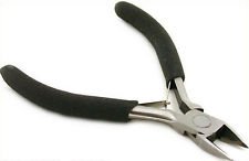
That indicates 'Sync' is running with a 25% duty cycle. I think the CPU is running OK. All this is pointing to a bad 6545 CRT Controller. Are you handy with a soldering iron? You will also need some solder wick, some solder, a 40 pin DIP socket, and a pair of small dikes (diagonal cutters). A small pair of needle nose pliers may also be handy. The dikes will be used to cut the legs off all 40 pins of the part to be replaced. This will be done so that unsoldering the individual legs with the help of solder wick can be performed with minimal heat applied to the PCB. You do not want to ruin the PCB by overheating. Is this something you can do?


cutters.jpg
 
That indicates 'Sync' is running with a 25% duty cycle. I think the CPU is running OK. All this is pointing to a bad 6545 CRT Controller. Are you handy with a soldering iron? You will also need some solder wick, some solder, a 40 pin DIP socket, and a pair of small dikes (diagonal cutters). A small pair of needle nose pliers may also be handy. The dikes will be used to cut the legs off all 40 pins of the part to be replaced. This will be done so that unsoldering the individual legs with the help of solder wick can be performed with minimal heat applied to the PCB. You do not want to ruin the PCB by overheating. Is this something you can do?
View attachment 21515

I have everything except a 40 pin DIP socket. I've done a lot of soldering, but never had good luck with a braided soldering wick, even with flux. Are there any wicks that are better than others?

The existing 6545 on my PET doesn't use a 40 pin DIP socket, so what is that for? There are a couple other chips on the board that have it. Why do some have it and some don't?

So, I should try to find a new video chip? I've searched for 6545, but can't find anything. An above poster mentioned a 6845 or HD46505? On ebay, I've found MC6845P and HD46505SP. Will any of these work?
 
Actual Commodore MOS 6545 chips are rarely on ebay, but the Rockwell version R6545xxx (where xxx is AP or EAP etc) is pretty common. So is the HD46505. There is also 68B45 or HD68B45. They should all work.

Commodore were not very consistent about which chips they socketed, so sometimes you will find the chip soldered directly in. As has been mentioned, be very careful removing unsocketed chip as heat buildup can ruin the traces.

Steve
 
I've done a lot of soldering, but never had good luck with a braided soldering wick, even with flux. Are there any wicks that are better than others?

Any product should do. I even used Radio Shack Desoldering Braid. Start with a clean end and place over the feedthrough hole. Apply soldering iron to braid and melting solder from the board should run up the braid. Some people have good luck with 'solder suckers'. See this wiki article on desoldering.

The existing 6545 on my PET doesn't use a 40 pin DIP socket, so what is that for? There are a couple other chips on the board that have it. Why do some have it and some don't?

After going through the trouble of removing a 40 pin part, using a socket will eliminate the need to ever unsolder that part again. But it is not mandatory. If you do, use a good one like this with gold contact finish:

http://www.digikey.com/product-detail/en/110-93-640-41-001000/ED3640-ND/81809
 
I always use a socket, out of fear of overheating the chip upon soldering. I know full well that I can safely solder just about anything without frying it, but still do it anyway. Sockets are cheap, and you will be happy with yourself for using one.

I too have never had great success with desoldering braid. With the cheap (manual) solder sucker that Radio Schack sells, I can safely and quickly desolder any DIP chip without damaging it. Buy two of them though, they break easily.

The trick is in the technique:

1) Re-tin each pin before attempting to desolder.
2) Heat a pin just enough to completely melt the solder on it. This takes practice to get just right.
3) When the solder is melted, remove the iron, and quickly put the sucker all the way over the pin, squarely against the board, with pressure; and push the release button. If you keep the sucker squarely pressed against the board, and the tip of the sucker is in good shape, most, if not all, the solder will be removed.
4) Use a solder tool, or a screwdriver, to make sure the pin is mechanically free. If it's not, keep pressure on it, and apply heat with the soldering iron. When the pin comes free, wiggle it as the solder hardens so that it doesnt get stuck again.

This isnt as hard as it sounds, and can be done very well with patience. I have no trouble desoldering and re-using the most sensitive chips this way.

It will help if you cut the chip off the board first, but I usually don't bother. It's easy to damage a board doing this anyway.

Also, desoldering on a PCB should almost never be done with a heat gun or 250W soldering gun. I couldn't tell you how many times I've had to repair a board when someone else did that.
 
Last edited:
Back
Top