• Please review our updated Terms and Rules here

Commodore LCD resurrection and the C128

RobertB

Veteran Member
Joined
Mar 20, 2006
Messages
986
Location
Visalia, California
Though the Commodore LCD was never produced, there are a few prototypes still surviving with CBM engineers Jeff Porter and Bil Herd. To my surprise, Steve Gray and Mike Naberezny, et al, are trying to build a Commodore LCD out of currently available parts! And the Commodore 128 is part of this LCD resurrection! To read more about the Commodore CLCD Project, go to


Writing from Portland, Oregon,
Robert Bernardo
Fresno Commodore User Group - http://www.dickestel.com/fcug.htm
Southern California Commodore & Amiga Network - http://www.portcommodore.com/sccan
 
This is definitely an interesting project. I’m familiar with Steve’s other CBM projects, and he has created some interesting things. And, of course, I’ve seen Bil’s prototype when he has brought it to VCF East.

I’ll be watching with interest.

Thanks, Robert!
 
... It's a little weird how this design uses the VDC chip from the Commodore 128 even though it looks like the LCD originally had memory-mapped video? I guess there's probably a reason for that (familiarity?) but I wouldn't call a VDC a "currently available part". (I mean, yeah, you can get one off eBay, but assuming it's not a fake it's going to cost you and almost certainly was pulled out of a Commodore 128.)

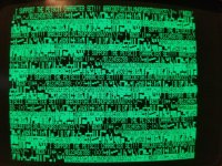
I've played with using the Commodore LCD's ROM fonts in a project; I have this homebrew video dingus on my workbench that I was thinking of building into a partial Commodore PET clone (getting the feeling that's a bit of an oversaturated market at this point, honestly), and because of pixel clock considerations I played with using the Commodore LCD's font instead of the PET font for the 80 column mode. (I actually had the system optimized for displaying 512 pixel wide TRS-80 graphics with a 12Mhz pixel clock, and 640 pixels wide is too wide for normal CTR overscan with that clock. The LCD's font gives you 80 columns in 480 pixels so it seemed like a clever way to go.) Here's the uppercase-only "Graphics" version of it in living green:

Commodore_LCD_font.jpg
 
Just for fun I spent a little time skimming through the specification sheets for the MMU and LCD controllers and the schematics, and I'm left wondering if CPLD they've chosen to use for the MMU might have enough gates left over in it to implement a simple monochrome video output which emulates the original. (There's not much to the original. It does plain text and graphics modes, and if you left out the unused 40 column LCD support the only thing that's a little odd about it are the horizontal/vertical scroll registers which act as address offsets.)

Composite output would be super easy, but if they wanted to go straight to the horse's mouth they do sell cute little 480x128 TFT LCD screens; most of them are too tiny, but this five inch one might be getting into the reasonable ballpark?. Reading the datasheet and it looks like it might not be *that* hard to drive one directly; you need a 9Mhz pixel clock and sync timing that (peculiarly enough) pretty much matches PAL TV standards. (It reads like logically it's like it behaves like a "strip" taken from a 4x3 panel.) The display takes 24 bit RGB data, but it'd be simple enough to just wire it up so it displays single-bit monochrome by driving the RGB pins via buffering. (You could even choose what colors you wanted for foreground/background.)
 
I just came across this thread. Some info and updates. We just got dumps of the ROMS from Jeff Porter's LCD machine, so we will try to support them if possible. The VDC in the design uses a latch to convert the VDC's DRAM interface to SRAM. Then we use Dual-Port SRAM that can be accessed by the VDC and the CPU at the same time, meaning the firmware writes directly to it's normal screen ram without going through the VDC registers. This was done to try to get a working system up and running as first steps. Yes, eventually we want to duplicate the custom LCD gate array and use an authentic panel, but suitable panels are very hard to find. The colour panel I chose is almost exactly the same size as the original. It uses an HDMI interface so we feed the RGBI output from the VDC through an RGB2HDMI and the result looks really good! The RGBI output is actually a standard NTSC format screen so it can be connected to a regular 1084 type monitor at the same time as it goes to the LCD panel (RGB2HDMI does an amazing job of scaling the video to fill the LCD panel). I recently finished the CASE as close as I could given existing pictures of Jeff and Bil's prototypes but now we have even more detailed pictures and even many measurements so I will be working to update the case to match Jeff's machine. Our prototype is booting to the machine language monitor as we have not yet implemented the MMU. More info and pictures can be found on my webpage.
 
Back
Top