• Please review our updated Terms and Rules here

Commodore Pet 2001 6550 - 6264 Ram adapter

Pet Rescue

Experienced Member
Joined
Dec 15, 2010
Messages
484
Location
Staffordshire, England
Hi all I have a quick question regarding a 6550 Ram adapter that I have seen on Nightfallcrew website.http://www.nightfallcrew.com/19/08/2014/commodore-pet-2001-6550-ram-adapter-by-xad-manosoft/

It is regarding the address lines on the 6264 Ram chip, address lines A2 & A3 joined and A4 & A5 are joined.
Both are joined at the 6264 side and the 6550 end, what is the reason for combining these lines?

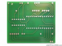
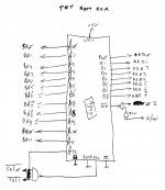
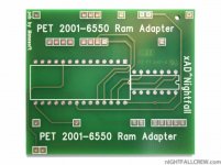
Here is the PCBram board 3.jpgram board 4.jpg6264 ram board.jpg
Another question is about the 6550 RAM chips for the Video RAM.
Am I right in saying you can replace the 6550 with 2114 RAM chips without any extra circuitry as the only difference is the clock signal to the 6550's
Whereas the The R/W circuitry is the same for both 6550 and 2114 from the Chip D2 74LS157 pin 7
 
Last edited:
Hi all I have a quick question regarding a 6550 Ram adapter that I have seen on Nightfallcrew website.http://www.nightfallcrew.com/19/08/2014/commodore-pet-2001-6550-ram-adapter-by-xad-manosoft/

It is regarding the address lines on the 6264 Ram chip, address lines A2 & A3 joined and A4 & A5 are joined.
Both are joined at the 6264 side and the 6550 end, what is the reason for combining these lines?

Probably because the 6550 is 1kx4 bits and the 6264 is 8kx8 bits, so joining one address halves the 8K to 4K and joining another address
halves again from 4k to 2k. So there must be another two addresses joined or more likely one address used as part of selection logic as the original
6550 also uses phi2 as select signal.

Here is the PCBView attachment 42067View attachment 42068View attachment 42069

Another question is about the 6550 RAM chips for the Video RAM.
Am I right in saying you can replace the 6550 with 2114 RAM chips without any extra circuitry as the only difference is the clock signal to the 6550's
Whereas the The R/W circuitry is the same for both 6550 and 2114 from the Chip D2 74LS157 pin 7

As I wrote, the 6550 uses phi2 as a select signal, so you really should make an adapter with a few gates to select the 2114 when phi2 is on the right phase (should be high, but don't quote me on this without verifying on the schematic). It might work without the phi2 signal if there's no bus conflict on the wrong half of phi2.

Frank IZ8DWF
 
The schematic looks straightforward but the pcb sure looks odd to me; hey, if it works...

I don't see any reason why you couldn't replace the video 6550s with 2114s without worrying about gating phi2 with /we, but I'd probably use a more reliable 2016/6116/9128 or equivalent instead.

m
 
If I may, when I saw that board, it reminded me about a blog repair on a Blue PET by one of our member here (scouter3d). In his blog, he built the board(s) which was originally from another VCF member too (Donni). When I was repairing my PET2001, Scouter3D was kind enough to send me a set of the boards. They worked and fixed my PET (I eventually replaced them with the PETVet due to newer Basic and 32k Ram). I thinked Manosoft just made a commercial-grade PCB. Here is the link to Scouter3D's blog: http://www.8bit-homecomputermuseum.at/repair/bluepet/bluepet.html

Scouter3D's board layout is different from that is in Nightfall's...you can see it from the zipped file from his site...it follows Donni's schematic.
 
Last edited:
Probably because the 6550 is 1kx4 bits and the 6264 is 8kx8 bits, so joining one address halves the 8K to 4K and joining another address
halves again from 4k to 2k. So there must be another two addresses joined or more likely one address used as part of selection logic as the original
6550 also uses phi2 as select signal.


As I wrote, the 6550 uses phi2 as a select signal, so you really should make an adapter with a few gates to select the 2114 when phi2 is on the right phase (should be high, but don't quote me on this without verifying on the schematic). It might work without the phi2 signal if there's no bus conflict on the wrong half of phi2.

Frank IZ8DWF

Thanks Frank if I'm understanding you correctly would that turn an 8k chip into a 2k chip using that board?
If so why would the designer willingly reduce the 8k Pet to a 2K machine wouldn't it make more sense to leave them in joined and get the full 8k?

Sorry for the questions I am still trying to get my head around how memory chips work.
The schematic looks straightforward but the pcb sure looks odd to me; hey, if it works...

I don't see any reason why you couldn't replace the video 6550s with 2114s without worrying about gating phi2 with /we, but I'd probably use a more reliable 2016/6116/9128 or equivalent instead.

m

Cheers Mike so I could just fudge a chip into the existing socket if I re route the relevant pins.
If I may, when I saw that board, it reminded me about a blog repair on a Blue PET by one of our member here (scouter3d). In his blog, he built the board(s) which was originally from another VCF member too (Donni). When I was repairing my PET2001, Scouter3D was kind enough to send me a set of the boards. They worked and fixed my PET (I eventually replaced them with the PETVet due to newer Basic and 32k Ram). I thinked Manosoft just made a commercial-grade PCB. Here is the link to Scouter3D's blog: http://www.8bit-homecomputermuseum.at/repair/bluepet/bluepet.html

Scouter3D's board layout is different from that is in Nightfall's...you can see it from the zipped file from his site...it follows Donni's schematic.


Thanks Riz I saw that site and downloaded the schematic and noticed the differences but did not know the reason why.
 
Thanks Frank if I'm understanding you correctly would that turn an 8k chip into a 2k chip using that board?
If so why would the designer willingly reduce the 8k Pet to a 2K machine wouldn't it make more sense to leave them in joined and get the full 8k?

Well, the 6550 is 1Kx4, the 8K 2001 has 16+2 of them to get 8Kbytes (+ video ram). I'm repairing a 2001 with 6540s and 6550s on these days too, so I'm starting to learn more about these chips. Previously I've always repaired the 2001N versions that use "normal" ROMs and RAMs.
I don't know why that adapter uses an 8Kx8 chip, but if it must be put in place of a single 6550 then it must be "reduced" to 1Kx4.
Of course the whole memory of an 8K 2001 can be a single 8Kx8 static RAM IC, but that means you have to "plug" on all the original RAM sockets (at least a few signals on most of them) or plug directly into the 6502 socket (so you need some adapters).
There're some adapter designs that let you use 2114 SRAMs in place of the 6550, 2114 have the same 1Kx4 size but they lack the 4 CS + PHI2 inputs present on the 6550, so the adapter incorporate some glue logic (single HCT138 usually) to adapt the 2114 select to the 6550 selects.
I'll be using this kind of adapters (selfmade) if I have to substitute 6550 RAMs in the 2001 I'm repairing (this has been decided together with the owner) and I'm also making a separate test circuit to carefully test each 6550 separately out of the 2001 motherboard, as the owner also has a few original 6550 spares.

Frank IZ8DWF

I'm in the same boat as yourself then, I have been mainly fixing the newer board pet's with the help of members on here.
I get a bit confused when it comes to memory circuits especially on the older boards.
I think that board is to replace all memory not just one 6550 as it taps into all the 6550's key lines.
When you compare the video ram parts of the circuit on the 2114 ram old boards that have 6540 rom's the circuitry are almost identical
apart from the 6550 ram chip.
I have a couple of Optimised Data Systems 4k Ram 6550 to 2114 adapter boards they use the 74ls139 to combine the clock signal.
It also says in the instructions that it can also be used for the video ram in U10 if you jumper pins 13,14,15 & 16 to the other video chip U11.
 
Back
Top