• Please review our updated Terms and Rules here

Commodore Pet 3032 no power

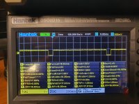
We are not looking at the pulse itself, but the time between two pulses.

Can you adjust the timebase to get two (2) pulses on the screen, then measure the time that the signal is LOW and the time between the two pulses (when the signal is HIGH).

Just make sure the voltage swing (top to bottom of the signal) is around 5V.

Dave
 
Top to bottom is 5V.
Here is a picture of that.
 

Attachments

  • 20230722_205011.jpg
    20230722_205011.jpg
    3.8 MB · Views: 5
That signal is fine. The problem is in the monitor then.

Can we identify exactly which monitor PCB you have?

There are multiple different monitor PCBs (as per usual with Commodore)...

Can you identify any numbers on the PCB and/or post a photograph?

Can you find a vertical position V.HEIGHT potentiometer fitted?

Dave
 
Thanks Dave!
I will take the monitor apart and get back to you tomorrow.
there is no visible V height potentiometer on the back, just brighness. But I'll will take a better look tomorrow ok.
 
Ok Dave!
The motherboard has following numbers.
Cdu-b79-cmd 9
And 2814311 Zb16m

I found the height pot. I can strech out the picture but its still garbage on the screen.
 
Excellent, so it is a 321446 and the component layout should look like this: http://www.zimmers.net/anonftp/pub/cbm/schematics/computers/pet/2001N/321446.gif.

The schematic should be here: http://www.zimmers.net/anonftp/pub/cbm/schematics/computers/pet/2001N/321445.gif.

The vertical section is the part of the schematic starting with a 3 (in a circle) on the left-hand side and going horizontally to the vertical deflection coils on the right-hand side (L601).

The numbers in circles identify the oscilloscope traces (and settings) you should get at the various points - as described in the documents: 321447-01 to 321447-10 you will find at: http://www.zimmers.net/anonftp/pub/cbm/schematics/computers/pet/2001N/index.html. In particular 321447-03 to 321447-07 for the vertical deflection circuit.

You shouldn't find anything here higher than 12V (the highest setting on the oscilloscope Y probe is 2 V/division).

All of the oscilloscope traces are taken relative to 0V/GND of course.

Dave
 
Last edited:
I would have a quick look at the following components first though:

C601, C602, C621, C651, C661 and C652.

R655, R656 and R657.

Just look at the capacitors 'by eye' to see if any look 'strange'...

Measure the resistors (with the PET OFF of course) to see if any have gone high resistance (or even open circuit). All of these resistors are low-values...

Dave
 
Thans Dave!
I'll will measure resistors and caps. I'll report back if I find anything.
 
Hmmm Dave!
R656 and R657 looks a bit odd.
R657 and R656 is 1 ohm. But I cant see the colorcode ,just one stripe (white) and and it almost looks burned. They are bigger than the other resistors.
Schematic says 1ohm
 

Attachments

  • Screenshot_20230724_111000_Gallery.jpg
    Screenshot_20230724_111000_Gallery.jpg
    1.3 MB · Views: 10
Last edited:
Maybe they should look like that. They seem to measure fine anyway... I cant see anything strange other than that. But I will take off those caps and mesure them.
 
Yes, they do look "odd" anyhow...

If they measure quite a low resistance value they are probably OK.

Resistors like this tend to burn out (and go open circuit) when a fault occurs, or naturally over time.

Dave
 
@daver2
I have recaped the board. I left two caps one 1uf 150V and one 6.8uf (non polarized?) They both mesured fine thou.
The resistors is fine.... Im a little scared to work with CRTs becouse of the high voltage. So im not sure if I can do the probing with the unit on!?

The recap did nothing. Its still the same picture.
Theres not mutch on that crt board. Could the flyback gone bad?
 
@daver2
I fixed it!!!!
The 7812 Voltage regulator gave me some strange output voltage! So I changed it and look at this! The picture got a bit more sharp after The recap aswell!
 

Attachments

  • 20230801_191525.jpg
    20230801_191525.jpg
    1.8 MB · Views: 4
Nice. I went for tea after reading post #113 and you fixed it!

Most people do jump to the conclusion regarding the flyback - but very rarely is it that. If I remember correctly, you had an image that was fine horizontally but not vertically. That pretty much rules out the flyback. You need the high voltages to display an image in the first place and the screen with was fine.

It is interesting that it turned out to be the voltage regulator though - but not unheard of.

I would check the DC voltage going into the regulator and look at the heatsink on the regulator. Too high a voltage going into the regulator, or too little heatsink can reduce the life of the voltage regulator over time.

Not that you need any advice anymore, but I was going to suggest attaching wires to the points you wanted to measure on the monitor board and bring these out of the monitor enclosure to a 'chocolate block' connector. You can then safely check the points with your multimeter and oscilloscope. On the vertical side of the monitor - the highest voltage is approximately 12V. However, this is now irrelevant if you have fixed it!

Dave
 
@daver2
You have helped me so mutch with this computer. Thanks! The links in post #127 was very helpful. Hopefully this computer will run for a while now.
 
Absolutely no problem. Glad to be of help.

The only thing you haven't tested now is the cassette port and the IEEE488 port.

There is a BASIC test program in the book "PET and the IEEE 488 Bus (GPIB)". Type it in and run it.

Dave
 
Ok. I found the book. I'll find the code and type it in.
BTW I have a old cassette deck for VIC20. Maybe I can use that to load a program. I found some wav files on internet. But I'll do the Basic test program first.
 
If you already have a cassette deck, type the BASIC program in, test the IEEE488 port and then try to save the program to (and load the program from) the cassette...

As you have the 'upgrade ROMs' (they display as '###') you might like to look into one of the many IEEE488 add-on disk storage devices for the PET. They work well...

Dave
 
Ok @daver2 the test program worked great.
When I run it I get the message blinking "End of test."
I can write the program to a cassette deck aswell. So now im gonna try to load a wav file...
 
Last edited:
Back
Top