• Please review our updated Terms and Rules here

Cromemco JS-1 Joystick Replica

Hi,

Okay, I have successfully taught ChatGPT how to write DZMBASIC programs ... this last bunch all came from slight modifications of the first ChatGPT OCTAGONS.BAS ...

From that program I made a few slight changes for HEXADECIMAL, PENTAGON and SQUARES programs ...

Now other people need to learn how to feed the correct instructions into ChatGPT and get working programs!

I wish ChatGPT could learn 8080 and Z80 assembly language better, but I keep running into the limits as I try working with assembly language programs.

20240912 DAZZLER Squares 2 Octagons2

This is so much fun!


.
 
Hi,

One of the subjects in the ZOOM meeting DAZZLER discussions was about "Screen Savers" ...

So I wrote one ... I may have to improve on it a little more tomorrow:


.
 
Hi, Here's a program listing for another type of screensaver:

0 REM Random DOTs on a Line LINES0.BAS.txt

10 REM Random Dots with Shifting Rows in DZMBASIC
20 RANDOMIZE : REM Initialize random number generator
30 GOSUB 1000 : REM Clear the screen
40 GOSUB 3000
90 GOTO 10
99 GOSUB 9000

1000 REM Clear the screen
1010 DZOP "C",16 : REM Set color to black
1020 DZOP "P",0,0
1030 DZOP "R",255,255 : REM Clear the screen
1999 RETURN

3000 REM Draw a new random row of dots at the top
3005 FOR Y = 255 TO 0 STEP -2
3010 FOR X = 0 TO 255

3020 COLOR = INT(RND * 7) + 17 : REM Random color between 17 and 23
3030 DZOP "C", COLOR
3040 DZOP "P", X,Y : REM Set position at the top row (y=0)
3050 DZOP "D" : REM Plot the random dot
3060 NEXT X
3065 GOSUB 1000
3070 NEXT Y
3999 RETURN

9000 REM End Routine
9010 FOR G = 0 TO 1
9020 PRINT CHR$(7)
9030 FOR PAUSE = 0 TO 499 : NEXT PAUSE
9040 NEXT G
9990 END

.
 
Hi,

Did a demo video of EXPLOSNS.BAS


This DAZZLER program is a little different ...

0 REM EXPLOSNS.BAS.txt

100 ' Initialize the DAZZLER
110 DZOP "I"
120 ' Explosion parameters
130 NUMDOTS = 200 ' Total number of dots in the explosion
140 MAXRADIUS = 50 ' Maximum explosion radius (half of 100-dot diameter)
150 ' Loop for multiple explosions
160 FOR EXPLOSION = 1 TO 10 ' Create 10 explosions with moving centers
170 ' Clear the DAZZLER display before each explosion
180 DZOP "Z"
190 ' Randomly set the center of the explosion within the 0-255 range
200 CX = INT(RND * (255 - 2 * MAXRADIUS)) + MAXRADIUS
210 CY = INT(RND * (255 - 2 * MAXRADIUS)) + MAXRADIUS
220 ' Loop to display dots in expanding radius layers
230 FOR RADIUS = 1 TO MAXRADIUS STEP 5 ' Gradually increase radius from 1 to
MAXRADIUS
240 ' Display a set of dots for the current radius
250 FOR I = 1 TO NUMDOTS / 10 ' Fewer dots at each radius
260 ' Random angle for each dot
270 ANGLE = RND * 6.28318 ' Random angle in radians (2 * PI)
290 ' Calculate X and Y position of the dot based on the expanding radius
300 X = CX + RADIUS * COS(ANGLE)
310 Y = CY + RADIUS * SIN(ANGLE)
320 ' Ensure X and Y are within 0-255 range
330 XPOS = INT(X)
340 YPOS = INT(Y)
350 IF XPOS < 0 THEN XPOS = 0
360 IF XPOS > 255 THEN XPOS = 255
370 IF YPOS < 0 THEN YPOS = 0
380 IF YPOS > 255 THEN YPOS = 255
390 ' Select a random color between 17 and 23
400 COLOR = 17 + INT(RND * 7)
410 ' Set the current color
420 DZOP "C", COLOR
430 ' Move cursor to calculated position and display dot
440 DZOP "P", XPOS, YPOS
450 DZOP "D"
460 NEXT I
470 NEXT RADIUS
480 ' Wait a short time between explosions
490 DZOP "W", 50
500 NEXT EXPLOSION
510 ' End the program
520 GOTO 120


.
 
>>> The D+7A boards analog outputs originate from its DAC and can put out a sine wave, but I'm not sure if the musical note system involved in the software referred to here, is doing that, or just outputting a square wave. The transistor amplifier in the Joystick box is an analog amplifier not switching amplifier. The circuit has no gain and is an emitter follower and follows the analog output from the OP amp fed by the DAC. A mild LPF would/could help the sound. My altered version of it has no gain either, it just converts the impedance.

@Hugo Holden / @nullvalue,

Good spot there about the emitter follower. I didn't spot that for some reason. However, if you look around the web, you will see two (2) designs for the JS-1. In one design, there is a 100 Ohm speaker between +5V and -5V. In the other design, there is a 45 Ohm speaker between +5V and 0V.

There is no doubt in my mind that the audio sounds 'better' in the case of the LM386 amplifier than with the single transistor emitter follower design of the JS-1. I wonder if there is an issue somewhere with half of the cycle being missing?

My music program outputs sine waves - well, four sine waves of the appropriate frequency for the notes summed together and NOT a horrid square wave.

In fact, the four 'voices' can have differently-shaped waveforms to give them a different timbre if required.

If you look back to post #361 of this thread you will find a link to a separate VCFED thread where we discuss the MUSIC program. This (in turn) contains a link to the Byte Magazine 1977 Volume 2 Number 9 issue where (on page 62) it describes the 6502 version of the MUSIC program. The Byte article also contains the hardware for the DAC, amplifier and (on page 76) the low-pass filter required. There may be some changes required to the filter schematic. It is expecting an analogue value in the range 0V to +5V, whereas the D+7A outputs +/- 2.x (ish) Volts (if I remember correctly) by default.

Dave
 
I have been checking my note transcription from the original Byte article and, apart from one minor error I have found (a duration of 15 instead of 16 - which appears to be not noticeable), I have a reasonably faithful transcription. I must, therefore conclude that the one major error I can hear is due to an original article error. I have looked through a small number of subsequent "Byte's Bugs" and found no mention of anything. However, the page from Volume 02 Number 11 (page 37) appears to be missing from the scanned article.

I will have a look around and see if I can find the actual music score online - or give it to one of my music friends and see if they can spot the error.

Dave
 
Hi,

Okay, got another step towards subroutines for the "Zombie Escape" game ... a sort of Etch-A-Sketch using keyboard inputs:

0 REM BLINK6.BAS.txt

10 REM Initialize DAZZLER and Clear the Screen
20 GOSUB 9000 : REM Clear the screen
30 X = 128 : REM Starting X position (center)
40 Y = 128 : REM Starting Y position (center)
50 CURSORCOLOR = 23 : REM Initial blinking color (white)
60 USERCOLOR = 16 : REM Default user color (black)
70 PREVX = X : REM Track previous X position
80 PREVY = Y : REM Track previous Y position

100 REM Main loop
110 GOSUB 200 : REM Draw the blinking cursor
120 GOSUB 300 : REM Wait for keypress and move cursor
130 GOTO 110 : REM Repeat the loop

200 REM Subroutine to draw blinking cursor
210 DZOP "P", PREVX, PREVY : REM Position at previous position
220 DZOP "C", USERCOLOR : REM Set previous dot to user-selected color
230 DZOP "D" : REM Draw the previous dot
240 PREVX = X : REM Update previous X to current
250 PREVY = Y : REM Update previous Y to current

260 DZOP "P", X, Y : REM Position at current X, Y
270 DZOP "C", CURSORCOLOR : REM Set color for blinking cursor
280 DZOP "D" : REM Draw the cursor dot

290 RETURN

300 REM Subroutine to handle keypress and move cursor
310 PRINT "Enter direction (L, R, U, D): ";
320 INPUT DIRECTION$ : REM Get direction from user

330 PRINT "Enter steps (1-999): ";
340 INPUT STEPS : REM Get number of steps (1-999)
350 IF STEPS < 1 OR STEPS > 999 THEN PRINT "Invalid steps!" : RETURN

360 REM Handle direction and move cursor
370 IF DIRECTION$ = "L" AND X > 0 THEN X = X - STEPS : IF X < 0 THEN X = 0 : REM Prevent going off screen
380 IF DIRECTION$ = "R" AND X < 255 THEN X = X + STEPS : IF X > 255 THEN X = 255 : REM Prevent going off screen
390 IF DIRECTION$ = "U" AND Y > 0 THEN Y = Y + STEPS : IF Y < 0 THEN Y = 0 : REM Prevent going off screen
400 IF DIRECTION$ = "D" AND Y < 255 THEN Y = Y - STEPS : IF Y > 255 THEN Y = 255 : REM Prevent going off screen

410 GOSUB 200 : REM Draw the new blinking cursor at the new position

420 PRINT "Enter color (1-8 for colors 16-23): ";
430 INPUT COLORNUM : REM Get color number from user
440 IF COLORNUM >= 1 AND COLORNUM <= 8 THEN USERCOLOR = 15 + COLORNUM
450 RETURN

9000 REM Clear the Screen Routine
9010 DZOP "C", 16 : REM Set color to black
9020 DZOP "P", 0, 0 : REM Position cursor at (0, 0)
9030 DZOP "R", 255, 255 : REM Fill the screen with black
9040 RETURN

.
 
Merry Christmas to everybody in the thread!

I am just trying to get audio (i.e. analog output) working with my D+7A board, and found a somewhat strange part in the circuit, which dosn't make sense to me.

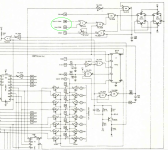
I got a rev. C board, which means there is no polarity option (as it is for the rev. E boards). But there is also another difference between rev. C and rev. E, which irritates me. The part of the circuit which triggers the MC1408 SAR IC and activates charging the analog output capacitors depends on the status of the S100 bus signals pSYNC and sOUT plus selecting one of the analog ports via the address lines, which makes sense. But - for me surprisingly - also on the data lines DO4 and DO6.

1735217398565.png

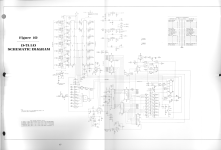
This is not the case for the rev. E layout. I have no idea why in rev. C data lines DO4 and DO6 (also labelled as "(SOUT)" and "(SIN)") are used as part of activating the analog output, and nothing about them is mentioned in the docs. Does anybody have a clue? Rev. C full schematics attached.

Correction: the SAR IC is an AM2502, not the MC1408 (which is the D/A converter).
 

Attachments

Last edited:
Yes, a Merry Chirstmas to everyone.

I have just had a glass of fairly strong alcoholic wine; so no driving, operating heavy machinery, or working on vintage computers!

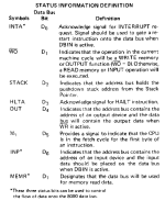
On an 8080 CPU, status information is output on D0 through D7 during part of the bus cycle transaction. In order to maintain compatability with an 8080 CPU, all S-100 cards 'should' mimic this behaviour.

It is just possible that compatibility with an 8080 CPU went out of the window in later revisions of the Cromemco cards? Just thinking about possibilities.

I suspect there is extra logic on the Z80 CPU card to generate the S-100 signals in the first place?

Dave
 
Yes, they have gone with the two physical S-100 signals on the Rev. E board (for the equivalent logic) rather than those derived from the data bus equivalents.

I am surprised that you are having problems though. What is your CPU board on your specific system?

Dave
 
Yes, a Merry Chirstmas to everyone.

I have just had a glass of fairly strong alcoholic wine; so no driving, operating heavy machinery, or working on vintage computers!

On an 8080 CPU, status information is output on D0 through D7 during part of the bus cycle transaction. In order to maintain compatability with an 8080 CPU, all S-100 cards 'should' mimic this behaviour.

It is just possible that compatibility with an 8080 CPU went out of the window in later revisions of the Cromemco cards? Just thinking about possibilities.

I suspect there is extra logic on the Z80 CPU card to generate the S-100 signals in the first place?

Dave
You are absolutely right, the 8080 writes status information during the beginning of each machine cycle. Here is an excerpt of the 8080 datasheet:
1735224378066.png
Again learned something new.
 
Yes, they have gone with the two physical S-100 signals on the Rev. E board (for the equivalent logic) rather than those derived from the data bus equivalents.

I am surprised that you are having problems though. What is your CPU board on your specific system?

Dave
I have a 8080 installed. The problem I have is that the analog output is not controlled by the port writes, or to be more precise, there is negative voltage on all analog outputs which won't change when writing to the analog ports and which is slowly increasing.

The digital port in fact has a diferent problem, output works perfectly, but input doesn't give any other value than F0 (probably indicates there is no activity on the D+7A anyway for digital inputs). Assumably not related to the problem with the analog outputs.

So, in principle, board addressing works. Also generation of the analog signal which is created by the MC1408 D/A converter in principle works in that it follows the port input with a linear response.

By the way, in post #389 I was mistaken, the SAR is the AM2502, not the MC1408.

I suspect that the analog output from the MC1408 does not reach the voltage copiers behind the multiplexer, so that the capacitors will not get charged. I am right now focussing on the activation chain for the multiplexer, going systematically through all the gates outputs. I was just confused by the DO4 and DO6 inputs, which I couldn't explain.
 
Last edited:
Well, we can explain it now...

There are a few other 'tricks' that the 8080 (and Z80) have up their sleeves with I/O instructions. Like outputting the B register on the high byte of the address bus when performing an I/O instruction using register C as the I/O port address (on the low byte of the address bus). I know of hardware that use this known 'fact' and process the upper byte of the address bus...

Dave
Very interesting, and thanks for the immediate support! Now let's get back to the drinks...
 
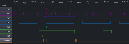
@daver2 The magic behind was that the previous owner had modified the D+7A board, so that the signals got into some kind of race condition. As you can see the in the logic trace, the AM2502 SAR never gets triggered because the rising edge of the 2 MHz clock signal (IC28P3) never hits an asserted state of port I/O transfer (IC28P2), so that the flip-flops in IC28 never propagate an I/O event, and thus never activate the AM2502 SAR, which again stops the "D/A engine".

1736009581246.png

The cause is in a modification, sourcing the clock signal from the S100 CLOCK signal (S100 pin 49) instead of the S100 PHI2 system clock signal (S100 pin 24), which doesnt work for me in my IMSAI system because the S100 CLOCK signal has a different phase. I wonder what might have driven the previous owner to do that modification. Maybe revision C of the D+7A didn't work reliably with a Z80 system with more than 4 MHz. Guess Cromemco fixed this with revision E.

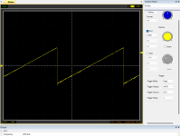
Anyway, after restoring the original state of the board, here is now what it should look like with a small test program creating a saw tooth wave (perfect linearity):

1736009815837.png

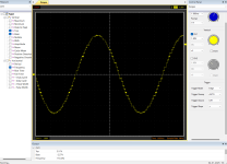
And another one with a sinus wave:

1736009911451.png


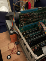
For audio output obviously a low pass filter should be added, as already discussed in the thread. But it already makes a lot of noise :)

1736010285123.png
 
Last edited:
>>> I wonder what might have driven the previous owner to do that modification.

Who knows?

I assume you have tried my 'music' program?

Dave
 
Back
Top