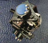
I got my Kraft controller today and had an opportunity to take it apart. As you can see, the joystick mechanism is completely different from the original JS-1. It looks similar to the one cjs posted in #58, but not quite.
I took some readings of the pots for comparison and we may have a small issue.
For both Kraft joysticks and in both directions, I got resistance from ~ 0.71K to ~1.4K
For the JS-1 joystick, in one direction I get the exact same reading. However, in the other direction I get readings of 0.84K to 1.62K.

") I was waiting until I got the enclosure to see if the joystick/gimbal needs to be moved back any due to height restrictions inside this slightly shorter case. Did you get your enclosures yet? Mine haven't even shipped. Was the joystick inside your Kraft controller the same as mine that I posted?
I was waiting until I got the enclosure to see if the joystick/gimbal needs to be moved back any due to height restrictions inside this slightly shorter case. Did you get your enclosures yet? Mine haven't even shipped. Was the joystick inside your Kraft controller the same as mine that I posted?