Hello,
Through a very unlikely chain of coincidences, I recently acquired an original Data Disc Model 7206 hard disk. In this post, I will outline what I’ve discovered so far, along with my plans and goals for this project.
From what I’ve gathered, this hard disk was originally designed to work with a 1211 disk controller for the PDP-8. Unfortunately, I only have the hard disk itself, though it appears to be complete and in good condition. Documentation on this model or its interface with external devices has been extremely hard to find.
My long-term goal is to attempt to activate this disk and recover any data that might still be present. I’d greatly appreciate any advice or insights. Please note, however, that this project falls outside my area of expertise, so I am learning as I go. One major hurdle I forsee is the need to reverse-engineer the architecture and signaling of the external connectors, as this design is by now quite prehistoric. More details on this below.
Summary of what I’ve discovered about the disk so far (approximately chronological):
My current focus is reverse-engineering the external pinouts and controller circuitry to understand the signaling needed to communicate with the drive. However, this is far outside my current skill set, so any documentation or guidance would be invaluable.
To aid in this process, I’ve attached:
If anyone has experience with this kind of hardware, similar systems, or can help with reverse engineering and documentation, I’d be grateful for your help. I’m happy to provide additional photographs, disassemble components, or answer any questions you may have - .
Thank you in advance,
Kuba
Attachments:
Labels:
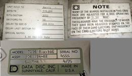
Disk assembly:
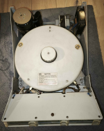
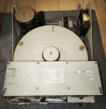
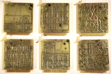
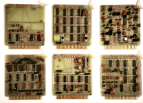
Controller rack, connectors, boards from the controller:
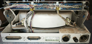

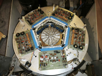
Drum insides:
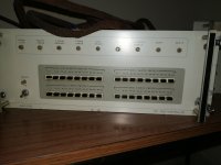
External controller (which i don' have):
The only bit of documentation I have:
Through a very unlikely chain of coincidences, I recently acquired an original Data Disc Model 7206 hard disk. In this post, I will outline what I’ve discovered so far, along with my plans and goals for this project.
From what I’ve gathered, this hard disk was originally designed to work with a 1211 disk controller for the PDP-8. Unfortunately, I only have the hard disk itself, though it appears to be complete and in good condition. Documentation on this model or its interface with external devices has been extremely hard to find.
My long-term goal is to attempt to activate this disk and recover any data that might still be present. I’d greatly appreciate any advice or insights. Please note, however, that this project falls outside my area of expertise, so I am learning as I go. One major hurdle I forsee is the need to reverse-engineer the architecture and signaling of the external connectors, as this design is by now quite prehistoric. More details on this below.
Findings So Far
Summary of what I’ve discovered about the disk so far (approximately chronological):
- Basic Information:
- This specific unit dates to March 1975, though I believe the design itself originated in 1971.
- It was sold to Harris, which makes its appearance in my part of the world a bit of a mystery.
- The drive is a single-platter, fixed-head disk with 64 tracks and 8 spare tracks, divided into 40 sectors. Each sector holds 2,722 bits (110,000 bits per track).
- The drive operates at a bitrate of 3.3 MHz, which is relevant to all printed circuit boards in the internal controller as well.
- Physical Structure:
- Power Supply: 120V, 50Hz AC via an Amphenol socket.
- Motor and Drive Assembly: Includes a large transformer at the rear, a 1/20 HP electric motor, and a precision drive belt connecting the motor to the main disk spindle.
- External Signal Connectors: Two Amphenol connectors (50-pin and 36-pin, seemingly Centronics-compatible). Not all pins are wired, especially on the 36-pin connector.
- Controller Assembly: A six-slot rack of printed circuit boards, primarily containing Signetics quad-gate ICs and flip-flops. One board appears to handle spare track and sector assignments using a jumper wire matrix. I assume the controller translates addressing into signals for the fixed-head arrays.
- Disk Drum and Heads:
- The main disk drum includes the platter mounted on a large bearing, which seems functional and free of major issues. The platter is surrounded by 2 steel rings above and below, with five circuit boards mounted on each. These boards connect the controller outside and to the physical magnetic heads.
- The heads appear to be handcrafted with extremely fine wiring, making them delicate and hard to access without risk of damage.
- The disk itself is in good condition, with no visible scratches or damage except for a small crater, likely the one already marked as a spare track in the spare track assignment sticker.
- A potential concern is a high-pitched resonant vibration when manually spinning the disk at low speeds (20–60 RPM). This might not occur at the designed operational speed of ~1,500 RPM, but I’m unsure if the bearing is self-centering as intended and if the vibration mode is only present at low speeds.
Challenges
My current focus is reverse-engineering the external pinouts and controller circuitry to understand the signaling needed to communicate with the drive. However, this is far outside my current skill set, so any documentation or guidance would be invaluable.
To aid in this process, I’ve attached:
- Photographs of the full assembly, all visible labeling, and both sides of the six printed circuit boards in the controller, and the external controller i don't have.
- A quoted excerpt I found on this forum, which is the only written information I have on this drive so far.
If anyone has experience with this kind of hardware, similar systems, or can help with reverse engineering and documentation, I’d be grateful for your help. I’m happy to provide additional photographs, disassemble components, or answer any questions you may have - .
Thank you in advance,
Kuba
Attachments:
Labels:

Disk assembly:


Controller rack, connectors, boards from the controller:


Drum insides:

External controller (which i don' have):

The only bit of documentation I have:
"A disc-oriented system has been constructed for mass data storage and retrieval to aid on-line evaluation of the Argus algorithms. A fixed* head, 64-track, 6.4 megabit disc (Data Disc 7206) was interfaced to an 8K, 1.6 VB processor (DEC PDP-8L) via the single-cycle data break channel. Each disc track contains 32 blocks of 256 thirteen-bit words (twelve data bits plus parity), providing a total disc capacity of 2048 blocks, the equivalent of four standard LINC tapes.An lOT instruction initiates reading or writing of one block of disc data whose address is specified by the contents of the PDP-8 accumulator (0-3777(base8))' A separate lOT instruction is used to set the initial data transfer core location (modulo400(base8)). A program interrupt is generated upon completion of disc transfer and additional lOT instructions test for parity error and transfer comple* tion. Worst case access time for a block of data is 33.3 ms and the transfer time is 1,024The maximum attainable data transfer rate is 16 blocks in 33.3 ms and occurs when requested block addresses are sequentially increased by two (modulo 40(base 8))' In order to allow concurrent processing and disc transfer, the interface contains a four-word circular buffer between disc and core memory. This buffer allows operation under worst case conditions when a data break request occurs shortly after the beginning of an lOT instruction which is followed by a memory reference instruction with indirect addressing."Washington University 1971 Progress Report No. 7 Biomedical Computer Laboratory
