• Please review our updated Terms and Rules here

DECtape adventures (Restoring a TU56 and TD8-E)

TJ_Mossman

Experienced Member
Joined
Dec 1, 2013
Messages
370
Location
Bristol, England
Hi All,

Recently I bought a TU56 for my PDP-8/e setup, so thought why not document my progress here?

The story so far...

July 6th: Bought Drive from Al Kossow.
August 8th: Drive safely arrives in Britain via DHL, thanks to some help from Bob Rosenbloom and his son with packing.
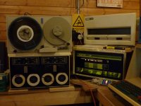
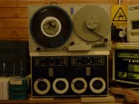
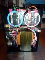
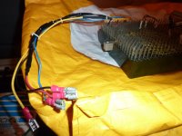
1.jpg2.JPG

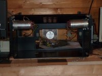
August 20th: I opened the drive up to perform an initial inspection...
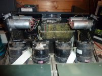
3.JPG

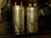
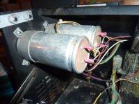
Motor run capacitors. Note some signs of leakage and cable fraying.
4.JPG

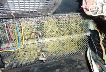
The backplane looks good...
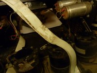
5.JPG

However it looks like some mice got inside and chewed some wires at some point.
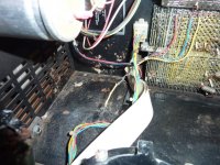
6.JPG

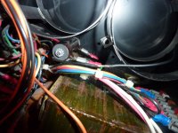
PSU removed and cleaned. One of the wires running alongside a dropper resistor looks like it got pretty hot and had its insulation burned off.
7.JPG

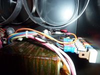
Repaired with a few layers of heatshrink, and moved the other wires out of the way. I seem to recall David Gesswein's drive having this problem too. Was this a common problem when they were in active use? As I understand it my drive is a rather late revision, being from '78.
8.JPG

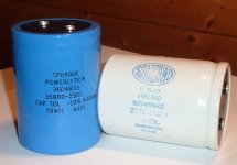
Original capacitors. No signs of leakage, so I tested them externally and they still appear to be within spec.
9.JPG

PSU re-assembled.
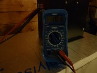
10.jpg11.jpg12.JPG

Supply voltages tested out OK.
13.JPG

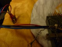
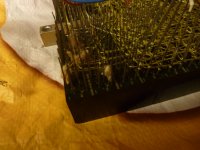
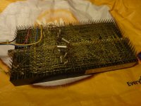
Removed the backplane for inspection and cleaning... Looks like some cables got chewed, and there was some signs of nesting material. The wirewrap itself looked fine though fortunately.
14.JPG15.JPG16.JPG
 
"Fixed". Kludgy but it'll do for now, at least until I find some fresh wire in the right gauge and colours.
17.JPG

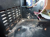
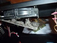
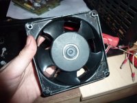
More grime... The fan was a bit hairy too.
18.JPG19.JPG20.JPG

But no more!
21.JPG

All in all it cleaned up very nicely. What I was worried was rust turned out to just be dirt.
22.JPG

I got some replacement motor run capacitors on eBay. These turned out to be a very close replacement. They're both the same spec and size as the originals.
23.JPG24.JPG

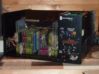
Cards and PSU re-installed.
25.JPG

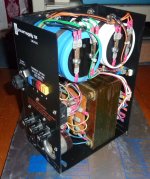
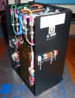
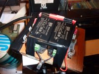
Normally the TU56 requires either +5v or +10v along with -15, supplied by a H716 mounted externally. Since my unit didn't come with one, I rigged up a replacement using MPM-30-15ST 15v and MPM-30-15ST 5v power supplies. I wired them in series, using the positive terminal of the 15v and negative terminal of the 5v supplies as a common ground. I also added fuses to match the H716. It's rather ugly right now, but later I'll build an enclosure for it, or see if there's space to mount it in the drive itself without having to modify any of the metalwork.
26.JPG

Here's a video summery of the work up to that point, and what happened after powering it on: [video]https://streamable.com/xq79gr[/video]
 
September 4th:
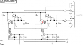
While troubleshooting the left motor on the left drive, I discovered that the G847 for that drive had a bad MPSA55 transistor at Q5. The base and collector showed a dead short.
27.png

I then installed the card on the other drive to make sure it worked, and it did. However, when I connected it to the left drive it blew the fuse again.
It turned out one of the G848s had a shorted capacitor and a bad 2N3715. After doing this, all 4 motors ran correctly in local mode in the hold setting.

My drive had neither the M960 + M961 interface cables, nor the G742 jumper card. After looking around for a bit, I saw Vince's redesigns of the M960 + M961, and was lucky to find he still had some left.

September 18th:
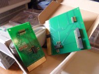
Vince's boards arrived, so I assembled them and also built a replacement for the G742 using a spare Flip-Chip extender I found on eBay.
28.JPG29.JPG

September 21st:
I work weekends so had to take a bit of a break, but I now had time to test things out. Vince kindly sent me some ribbon cable and IDC connectors along with the boards, but since I didn't have a crimping tool I borrowed the cable from my RX01 for now. In the mean time I'm using Kyle Owen's os8diskserver utility to boot off an emulated RK05.

At that point I could read, write, and format tapes on the right drive.
Presumably the alignment can't be too far off either as it's letting me read and write a tape I bought off eBay that already had a valid OS/8 structure and some files. (Speaking of which, if anyone knows what "CLICK-CLICK V2" is, let me know)

The left drive worked momentarily before blowing a fuse on the G847 again. I think I got as far as doing a directory listing before the right motor failed. A 2N3715 in the same location as before on the G848 appears to have failed, and I wasn't sure what had caused it yet. Swapping both G848s and the G847 lets me use the left drive, but since swapping them it doesn't seem to recognise pre-written media. It did however let me use a tape after formatting it.

Apart from that I still had a bit of debugging to do with the controller itself before it will pass the MAINDECs. ISTR bit 4 of the command register appearing to be stuck.

September 24th:
Hmm, so this is strange: on the pair of G848s I have that work, the TO-3 transistors Q5 + Q7, along with Q6 + Q8 each have a plane/trace on each side of the board that bridges the collectors of the pair of transistors. On the top side, each pair of transistors connects to a diode, and on the bottom side they connect to a pin on the molex connector like so:
30.png
However, on the pair of G848's that I've been having issues with, instead of the transistors being connected directly to the PCB, there's a mica sheet insulating the collectors from the top side of the board, and lots of thermal paste over the screws. On one board, the collectors on both pairs of transistors had no continuity with the top layer, thus disconnecting the diodes from the circuit.
On the other troublesome board, the thermal paste on the screws appeared to prevent the collectors from being connected to the pins on the molex connector.
One board has DEC transistors all with the same date codes, so I'm guessing this was done at the factory. I'm not sure if these boards ever worked to begin with?
Either way, cleaning the gunk off the screws seemed to solve it.

Meanwhile my TU56 restoration has turned into a game of whack-a-bug: I finally seem to have two good pairs of G848s after dealing with the poor connection between each side of the board, and, rather embarrassingly, realizing that the thermal paste I'd used was not as "non-conductive" as the label had said. Needless to say things got very hot, and I now have a nice TO-3 shaped burn mark on my hand. :mad:

After that I read a tape on the right drive, just to make sure I'd not done anything, and tried to write a file to it. This turned out to be a mistake, as somehow doing so has ended up corrupting it, leaving me with a bad directory structure.

I then mounted a scratch tape that I've knowingly been able to format before, and am getting timing BLOCK NUMBER ERROR PHASE 4.

When running the TD8E MAINDEC it's apparent why - when set to display the block number in the accumulator for the tape I tried to format, every third bit appears to stick or glitch out. The tape I think I corrupted however appears to count up and down the blocks correctly.
[video]https://streamable.com/bh8f7p[/video]

September 25th:
Hmm, so going by the maintenance manual the drive uses 10 tracks arranged in redundant pairs: 3 data tracks and 2 control tracks. (one for timing and another for mark)
In my configuration, there are 5 G888 Manchester Reader/Writer Modules, one for each pair of tracks.

I found the G888 responsible for data track 2, hoping that swapping it for an adjacent one might move the bit error across to another track, but it didn't make any difference when trying to write to the tape and read back from it.
I suppose I'll have to see where else the signal to that bit goes...
 
Last edited:
My TD8E and TU56 were painful to get working. Mostly because the TD8E was scrapped by DEC and had never worked.

I have found some DECtapes that format fine in PDP-8 format, but get various Phase errors when trying to format them for a PDP-9. Try to format different tapes to see if some work OK and some get a Phase-4 error.

I tried a couple of tapes that were known to read, write, and format correctly on the 21st, but those were the tapes I stared having trouble with a few days ago.
I tried to format another tape just now, but now it doesn't even get as far as before with any tape. Now TDFRMT just gives me the "SETUP?" error before it can start the tape.

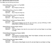
Indicates an error in the DECtape setup. One of the units specified is in write-lock position, not selected, or the write flip-flop is unable to be set, or there may be a timing error. (After message revert back to UNIT.)

I don't think it's to do with a bad write-lock switch/signal, since both drives were just able to write recently, and the selection logic seems fine too since the select lights do come on. I tried running the diagnostics again, and get:
TIMING ERROR SKIP INSTRUCTION AND LOGIC
TIMING ERROR STATUS BIT NOT SET IN COMMAND REGISTER

TIMING ERROR DOES NOT CLEAR WRITE FLIP/FLOP

Looks like I have yet more things to debug...
 
Hmm, it looks as if I may have found my first bad part - an SP380 at E17. The inputs on pins 11 and 12 both go low while trying to run the formatter, but the output (NORed) on pin 13 stays low.
Pin 13 feeds into pin 12 (D) of the Write flip-flop at E30.
 
Did you check the Mark Track Timing Generator for correct timing? Mine was off a little and caused problems when formatting tapes.
 
Did you check the Mark Track Timing Generator for correct timing? Mine was off a little and caused problems when formatting tapes.

I did, it seems pretty close at 8.41μs.

In the meantime I bought a cheapo logic analyzer so I could get a better look at things than with my 2-channel scope. I'm not sure if I'm onto something or going off on a tangent, but one thing I did notice is that the S/G flip-flop will enable when trying to list a directory or running the MAINDEC, but not when running the formatter. Now I'm tracing the signals back and trying to figure out just what it expects to see before it will start the tape moving.
 
Nice repair odyssey; it's always fun and instructive to watch this kind of detailed report. What did you use for the motor run cap replacements? I can't quite read the specs in your photos. Can you point to the eBay vendor you used?

I got a set of replacement caps several years ago that Dave Gesswein had commissioned because most of the caps available were of the wrong diameter. If you have found an easily available part that fits the original clamps, that will be helpful to know.

Jack,

Thanks, I'll have some more updates to it soon. The past couple of nights I've been busy with the logic analyzer, but so far haven't found anything suspect.

These are the ones I bought, and apart from having different spade connectors are a drop-in replacement: https://www.ebay.com/itm/142631210678
They're not the cheapest, but they are from a US based shop.

-Tom
 
Hmm, somewhere along the way I think the CPU has developed a fault...

I found Mike Thompson's simple TD8-E tests in another thread and tried checking the Command and Data Registers, and found that while the Command Register test appeared to run OK, bits 8 and 11 were stuck low when running the Data Register test. I adapted the program by removing the SDLD, CLA, and SDRD instructions, so I could try copying the SW directly from the AC to the MQ, and found that the stuck bits still persist.

00200 7200 CLA /Clear the AC
00201 7604 LAS /Switches->AC
00202 7421 MQL /AC to MQ
00203 5200 JMP 200 /Do it again
 
Yup, looks like there's a problem with my Major Registers board. Fortunately I have a spare that doesn't have this problem, but I might as well run all the MAINDEC's while I'm at it...
I can now at least confirm that the Data Register on the TD8-E works.
 
Last edited:
Since buying the logic analyzer, most of the chips that I'd initially suspected could have issues appear to be fine.
Meanwhile I found a copy of the TDFRMT source and produced a listing from it, from there I tracked down the errors that can cause the "SETUP?" error.

I found a copy of the source for TDFRMT so I could see what exactly was causing the "SETUP?" error. I noticed there's several things that can cause that error (the JMPs to ERCHK), so I replaced the first JMP ERCHK with a halt and sure enough it did halt there.

Code:
                      /SEE IF THE DRIVE IS OK
003224  6774  RSTSM,  SDLC            /LOAD CR TO CLEAR TIMEING ERROR
003225  6775          SDLD                    /LOAD DATA BUFFER TO CLEAR S Q FLAGS
003226  1162          TAD     DT0400          /SET WRITE
003227  1027          TAD     DTA             /GET UNIT
003230  3257          DCA     SAV             /STORE IT AWAY
003231  1257          TAD     SAV
003232  6771          SDSS
003233  5232          JMP     .-1
003234  6774          SDLC
003235  1257          TAD     SAV
003236  6774          SDLC                    /LOAD THE TRANSPORT
003237  6776          SDRC                    /READ THE COMMAND REGISTER AND CHECK IT
003240  7006          RTL
003241  7004          RAL
003242  7500          SMA                     /CHECK WRITE TO BE SET
003243  5260          JMP     ERCHK           /WRITE IS NOT SET  <<<---Halts here if changed to HLT.
003244  7004          RAL                     /CHECK WLO
003245  7510          SPA
003246  5260          JMP     ERCHK           /WLO 
003247  7004          RAL                     /CHECK SELECT AND TIMING ERROR
003250  7710          SPA     CLA
003251  5260          JMP     ERCHK           /SELECT OR TIMING ERROR
003252  4777'         JMS     NUDTA           /CHECK OTHER DRIVE IF ANY
003253  5213          JMP     RSTSM-11        /CHECK OTHER DRIVE
003254  5655          JMP  I  .+1
003255  1400          STMK
003256  0000  CNTERL, 0
003257  0000  SAV,    0

Does anyone have any hints on what I should check from here?
 
The game of whack-a-bug continues...

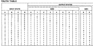
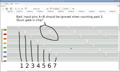
There's an 8251 BCD to Decimal decoder on the controller that interprets the instructions being sent to it by the computer. Rather than decode correctly, it always appears to be converting the two least significant bits to decimal, which produces an invalid state when counting past 4.
I'd actually suspected this a couple of months ago when I noticed the same thing with a logic probe, so I connected my analyzer to it to double-check it. Back then I couldn't reproduce it (perhaps the chip was temperamental then, or I had a poor connection on the clip?), but now it does it every time.

1.png2.png3.png

I bought a couple of spares on eBay, they're pretty hard to find now but there's similar enough 7400 series chips that I could probably build an adapter board for one if I had to.
 
4.png5.png

This probably explained the TIMING ERROR STATUS BIT NOT SET IN COMMAND REGISTER error I was getting when running the diagnostics. What's supposed to happen (if I'm interpreting it correctly) is the code generates a timing error, which is set as a flag in the command register, and is then in turn read into the accumulator before being saved in a memory location, which the rest of the code then refers to to run the tests.
If the controller is erroneously executing an SDST (skip on time error) while running an SDRC (read command register to AC), it's skipping over that DCA (save to memory) instruction because the timing error flag is set.

Either way, I swapped the 8251 and the error did indeed go away. After that the error in the MAINDEC went away, and TDFRMT could one again attempt to format tapes.

It always failed to read back the block number though, and looking at the block count it appeared that every 2nd and 3rd bit were behaving erratically. I've been tracing the signals back from ND0, ND1, and ND2 and found that the outputs driving ND1 and ND2 on the 8242 XNOR chip at E18 has failed.

I've swapped this for a known working one, but immediately afterwards a new problem has cropped up: the unit now fails to make it as far in formatting, and fails to read back the mark track.
Weirder still, If one drive is set to Unit 0 and the other is 1, telling Unit 1 to move will move both units. The diagnostics now fail with "NO SELECT ERROR STATUS FROM UNIT 1".
I suppose I'll have to look into the drive select logic next.
 
I have done many repairs where fixing one problem reveals the problem behind the broken part. It is a little frustrating, but it is rewarding to finally find all of the bad parts and get it working again.
 
I have done many repairs where fixing one problem reveals the problem behind the broken part. It is a little frustrating, but it is rewarding to finally find all of the bad parts and get it working again.

That's what I'm hoping for :)

Meanwhile I've tested the flip-flop for the unit select and it appears OK. I then followed the signal to a buffer, and have found that it doesn't always propagate a high signal.
6.png
The chip was already socketed, so I tried testing it out of circuit, and also swapping it with a known working one for good measure. I've not seen any change though, so I'm guessing something on the TU56 side is pulling the signal low, as it goes straight from the buffer to the ribbon cable.
 
The cable between the TD8E and the TU56 in my 8/e is flaky. Sometimes I don't get a unit select and have traced it to the contact in the ribbon cable connector where it plugs into the TD8E. I wiggle it, and it works for another 6 months.
 
Back
Top