• Please review our updated Terms and Rules here

decwriter II (LA36) with datasouth board - rs232 questions

iainmaoileoin

Experienced Member
Joined
Dec 24, 2014
Messages
216
Location
inverness
I have just obtained a decwriter II (LA36) 1977 is what the label on it says. After a bit of clean and tidy, check PSUs etc, in local mode the unit (almost works). I have a pin that does not fire when the carriage is towards the left. I think the ribbon cable is frayed/faulty - - anyway I can live/fix/work with that issue.

The unit has a datasouth board upgrade. (Yes it is a decwriter II not one of the OEM versions). The fitting of the datasouth board left a few of the cables with nowhere to tie down - I think the connectors moved position from the original dec board. I can find manuals for the decwriter, but not for the datasouth board.

I have a few questions if anyone can point me in the right direction:

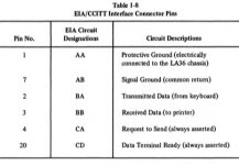
ONE I cant find any info about the RS232 (EIA) interface on the datasouth board - pin out etc. Can anyone help - what were/are the standard? (On the datasouth board I have an 20ma interface - documented, the rs232 not documented and a 25 pin "rs232" type connector).

TWO Some manuals seem to indicate the board can do 9600 baud. (The keyboard has buttons for 110/300 and press both for 1200). Am I reading newer manuals than the board version I have when it says 9600 is possible? Sure I can get the scope/data-analyser out and watch for signals.... that is a slow job for me. All clues/pointers welcome.
 
Some private email shows me that I have not asked the correct question. I dont have a serial cable coming out from the datasouth board. I dont know what the pinouts are on the mother board. So I need to graft that before I can do anything with finding speed, parity etc.

The connector on the datasouth board looks like the "standard" 20ma mate N lok/molex type connector that is used in this generation of kit. I have knowledge of the the RX/TX pins that the 20ma uses, but this board has a second connector of the same type as the 20ma connector - but with more pins wired up for the RS232. The unit does not appear to use one of the 20ma to EIA type convertors that DEC had, but puts "proper" EIA RS232 out on the second connector.

So I am trying to find what pins/signals that DEC used for RS232 on the 8 pin connector.
Below I have snippets from the manual... But it does not help me - does anybody know if the AA/BA stuff is relevant? I might have missed the key phrase in the decwriter manual. I have read it more than a few times now ;-(
 

Attachments

  • photo62211.jpg
    photo62211.jpg
    24.9 KB · Views: 4
  • photo62212.jpg
    photo62212.jpg
    21.5 KB · Views: 3
  • photo62213.jpg
    photo62213.jpg
    20.2 KB · Views: 4
Stuck. The circuit of the DEC board shows 5volt logic. That aint RS232. I dont know if the datasouth board was identical or came with a lead that did not need 5v<->+/-12v work.
The dec circuitry is shown below. In the absence of any datasouth info I guess I need to measure the voltages on the pins 2/4/5/6/7 and see whether the datasouth board is kind of drop in equivalent. I dont see any sort of CTS/DTR type signals on the DEC board. The datasouth has a UART so I may be trying to find a level converter/buffer to decide if the board takes +/-12 or needs a 'convertor' before I start.... Out with the magnifying glass and the 'scope....
 

Attachments

  • photo62214.jpg
    photo62214.jpg
    88.4 KB · Views: 2
First off - I know nothing about the Datasouth board(s) you are referring to.

On a 'standard' DEC card they used J3 for the 20 mA current loop and J4 to connect 'options'. One of the options was a 'proper' RS232 interface.

The signals on J4 provide TTL levels for serial out and serial in along with the requisite power supplies for the external interface. Nothing to do with RS232.

Table 1-8 in your post #2 is what you would connect an RS232 signal cable to - but on the option board that you would use that (in turn) plugs into J4 on the main logic board. The TTL signals from the main logic board are converted into RS232 levels by the option board.

The 'jumper' between pins 2 and 4 of J4 was only for maintenance testing. It is (effectively) a TTL seral loopback connector. It is not required for normal operation...

I have seen an 'updated' schematic diagram that does drive an extra pin on J4 for DTR.

Two possibilities present themselves:

1. Use a 5V TTL to RS232 converter module that you can purchase (designed for something like the Arduino Meg 2560). This will give you something that should be OK for RS232 that you can connect to J4 (assuming a 'standard' DEC J4 pinout of course).

2. Use the 20 mA current loop interface and an external current loop to RS232 converter. There are schematics for these available online - and you can still buy them...

The other option would be to do a bit more 'computer archaeology' and take some much higher resolution of the card(s) you have, post them on a file sharing website and link your VCFED post to them. Also, can you identify exactly what the identifying marks on the PCB actually are.

I don't recollect an LA36 at 9600 bits/second - however, later interface boards (or third-party boards) may have increased that. I am trying to think back 30 years to what we used at work. I think we had an LA120 - and that had a little seven-segment display that allowed you to use the SETUP key to configure the desired transmit and receive rates independently. That definitely used a rate of 9600. It is just possible that they keyboard still had the 'fixed' baudrate keys. But it is so long ago now...

Dave
 
The LA36 can't do 9600 bps. No interface board is going to change that. You'd need a computer in between with two serial ports and buffering in order to do the speed conversion.

I think the rest have been convered already.
 
The LA36 can't do 9600 bps. No interface board is going to change that. You'd need a computer in between with two serial ports and buffering in order to do the speed conversion.

I think the rest have been convered already.
I'm pretty sure the Datasouth board is microprocessor based and fully buffered. The question then evolves to what it uses for a baud rate generator and how you'd select that speed with only 2 buttons on the keyboard. I don't remember.

The Datasouth board makes use of the fact that the LA36 can actually print faster than 30CPS (in "catch-up mode" after a carriage return is performed). The Datasouth board runs the head at 120CPS-ish. Not all carriage motor / optical encoder assemblies ran reliably at that speed. Back in the day you could call up Jim Busby (founder and CEO) and he'd send you some secondhand motor / encoder assemblies to try. It's only held in with 2 screws into the motor baseplate.

That would require changing more stuff in there, basically ripping out the whole LA36 in itself. Because the printing speed is usually independent of the serial speed. It prints at a certain (maximum) speed, and if you were to increase that, you'd also need to change the timing on the printing pins. And if you've ripped out the internals, then I would suspect they just repurposed the speed select switches to mean other speeds.

120 CPS is more like the LA120, unless I remember wrong.

Of course, this is all very doable. Sounds like the Datasouth upgrade was a pretty nice one.
 
bqt, Terry, daver2: Thanks. I have not had time to get the voltmeter/scope out yet. This weekend I hope.

The adverts for the Datasouth board say it is a drop in replacement for the DEC board. Unless they supplied a RS232 lead/connector I guess that means the kit delivers TTL and needs converted for RS232. A 'scope will help show that. BUT I cant see why they have 7 connections when the DEC board did not do RS232 handshake?
The P8085 is the uproc, The M5L8155p is a parallel port beast - I was hoping it was a UART! M5L8212p is a 2K x 8 eprom/prom. A ha the AMD P8251A has RTS and DTR type signals. I wonder?


Somebody asked me to post links to some higher-res photos to give them a better chance to see the circuit.
http://www.inverness-bunker.space/decwriter.html has such photos. They are large images so - if like me - you live in a rural area where carrier pigeons are the data carrier, the download may be eh "a bit slow".
 
DEC didn't use the modem control signals for flow control. But that don't mean DEC didn't use the modem control signals to control modems... :)
 
There's '1488 & '1489 ICs on the board, so it should have an RS-232 level port to connect to the computer. You shouldn't need a TTL to '232 converter.

Tom
 
A picture paints a thousand words :)!

Use a multimeter (set to measure resistance) and, with the power off to the LA36, follow the RS232 in/out pins of the various buffers to the connectors (use the data sheets for the ICs to determine which they are. You can also follow the 8251 serial in/out to the 1488/1489 and then use the data sheet to identify 'the other side' of the associated RS232 buffer and then chase the PCB tracking from there.

Dave
 
That would require changing more stuff in there, basically ripping out the whole LA36 in itself. Because the printing speed is usually independent of the serial speed. It prints at a certain (maximum) speed, and if you were to increase that, you'd also need to change the timing on the printing pins. And if you've ripped out the internals, then I would suspect they just repurposed the speed select switches to mean other speeds.
The logic board (that the Datasouth DS120 board I'm familiar with replaces completely) is the only logic in the printer. It has complete control of printhead timing. The optical encoder on the carriage motor sends signals to the logic board that tell it when to fire the printhead pins. The logic board also provides the drive for the carriage motor. 120CPS is definitely doable, subject to the reliability of the optical encoder. Trivia: the LA36 does not have a "printhead home" detector - the logic (either DEC or Datasouth) just drives the printhead to the left until it stops seeing encoder pulses. That is assumed to be the home position until the power is cycled. You can actually grab the printhead and move it somewhere, then power on the LA36. If you prevent the printhead from moving, that's the new home position.

I think I mentioned that there was a hack to the DEC LA36 logic board to make it always print at 60CPS (permanently in "catch-up mode"), but you needed a host OS that could pad / delay printing until the printhead homed at the end of a line.

120 CPS is more like the LA120, unless I remember wrong.
See the ad titled "Tune up your LA36" here for specs.
 
Back
Top