NeXT
Veteran Member
Mention fuel and emissions control to people who lived through the 70's and early 80's with a car and for some reason the music of CCR and the sound of helicopters start going through their heads as if the Malaise Era was as traumatic to them as Vietnam might of been.
Basically in that period the ability to run an engine loud and rich was being clamped down on to deal with smog and fuel shortages. Initially it was devices such as anemic carburetors, smog pumps, the Exhaust Gas Recirculation Valve and pellet-type catalytic converters which either by design or their primitive nature restricted how well an engine could perform and gave themselves a really bad reputation for neutering a car's performance (while everyone else who was not a full-time automotive person didn't really care) but by the 80's the computer was starting to become more common in the automobile and while affordable fuel injection was still another half a decade away some people pushed on and tried to figure out what they could do to make the carburetor as efficient as you possibly could.
American Motors, the same company who brought you Jeep until Chrysler bought them outright and surgically killed everything but the Jeep brand off could not afford fuel injection R&D time. Instead they decided to develop a peculiar system as had other car manufacturers around the same time where the amount of fuel atomized by the carburetor was more precisely controlled electronically. Their electronic fuel feedback system was known as the Computerized Engine Control and consisted mainly of on and off sensors that monitored the engine and carburetor for various static states which in tandem with an O2 sensor located in the exhaust manifold would drive a two-phase stepper motor in the back of the carburetor to control how rich or lean the mixture leaving the carburetor was, plus later on additional control for ignition retard and various smog control components.
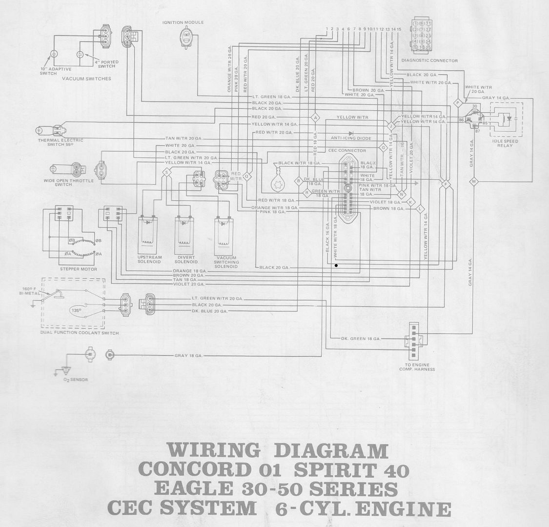
Now of course like with the people mentioned at the beginning of this article there are quite a few in the older automotive world who have no comprehension how a computer can help a car, much less how to repair it when things go sideways, which they will do, when you attempt to adjust your idle jets and you are unaware that each screw turn is being countered by the computer until the computer can't compensate anymore and now you're mad that your car runs like total crap. This is why half-baked procedures such as the Nutter Bypass exist so you can either run high-performance replacement parts in the fuel and ignition system or better peace of mind because "HOW DARE YOU LET A COMPUTER DO THE LORDS WORK IN A CARBURETOR! >:U" Carters' 2BBD units from the same period and attached to the same CeC system were just as willfully disrespected. Over the years it is likely many a carb has been swapped out either because of the above or because kitchen table carb rebuild generally result in poor results. Do it right, people. Admit when you are in over your head and have a shop do it if it comes down to it.
Anyways, when I purchased a 1982 AMC Eagle wagon it too was equipped with a 6-cylinder CeC system. Being more tech savvy than automotive this was one of the first parts of the vehicle to be serviced. Indeed much of it is digital on/off, with the exception of the O2 sensor. It's stupid simple. My money is on the Speeduino shields out there being just that much more advanced than we would ever need to make a 1:1 CeC replacement.
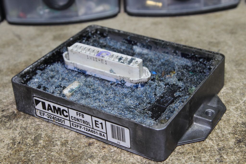
While I was able to confirm that it still could do its job well with a new O2 sensor I still had many questions regarding the computer itself. In an Eagle wagon this exists by the feet of your passenger behind a panel. While modern ECU's have nicely gasketed covers and a light conformal coating it was decided by AMC and ironically Ford who manufactured the computer to instead screw the board to the bottom of a die cast pan and fill it with blue dyed silica mixed epoxy.
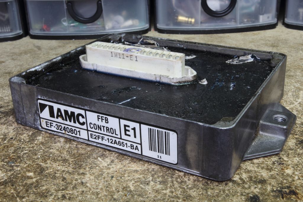
If I wanted to even start on the foundation towards making a modern replacement (pretty much functionally identical but the added ability to vary your "optimal" mixture and ignition retard which were both hard-coded on the original CeC) I would have to extract the board from its entombment. Normally removing potting is hard, due to the nature of potting compounds, however as I had observed with the Mastervoice ECU you can have potting batches that do not behave as they should and on the above donated computer the same now applied as the hard resin had begun to break down unto a rubbery but still softer material. This made it prime for boiling.
This is a depotting method that I have seen used before. Most epoxies at different temperatures will soften before more delicate components like large honkin' plastic harness connectors, or the IC's themselves.
In this case the computer was put in a stock pot filled with water and left on the stove for half an hour to cook.
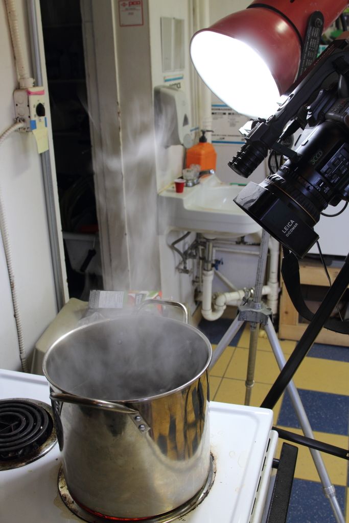
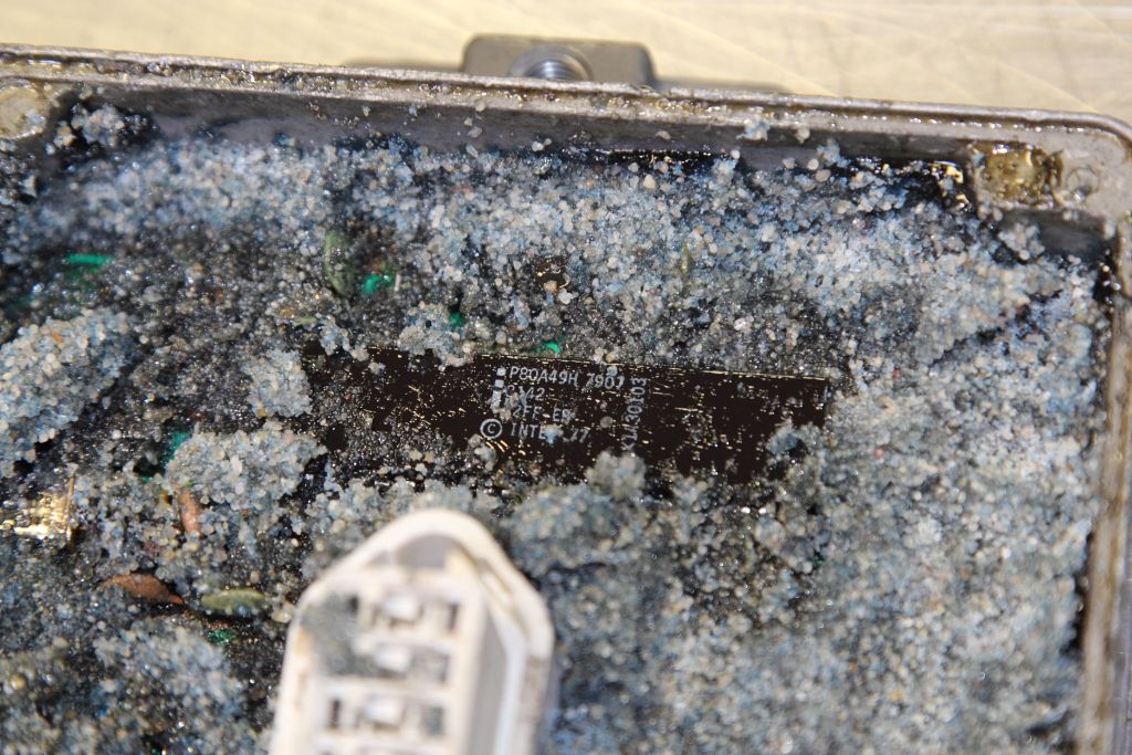
When it came out of the pot it was of course scalding hot to the touch but with merely a screwdriver the epoxy could be scooped out in large chunks. Almost immediately I was able to identify the heart of the CeC, an automotive-grade Intel 8049. The MCS-48 series was Intel's first microcontroller and remained IMMENSELY popular unto the 21st century.
Continuing deeper found more components of the lone circuit board, then as I began digging out around the sides of the board I realized there was four unused screw holes. It turns out that to save a few pennies they left those out and instead two torx heads live in the harness connector. That way the board is still secured in place and the strain from the harness would not flex the board. Once those were located and removed the module was reheated and then using a heat gun on one side the board was carefully pried up and out.
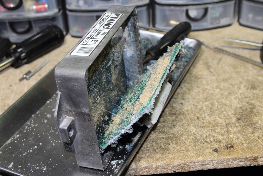
Now that I had the board released I paid attention to how the harness connector attached to the two-layer circuit board. If I wanted to better clean the board up it needed to be removed. At this point I want to point out that hot air rework tools like the Hakko 850 and its various clones work great for heating up and picking out smaller lumps of potting while still giving you the control necessary to not melt and burn nearby components. Once that was out of the way the connector was easily desoldered and pulled.
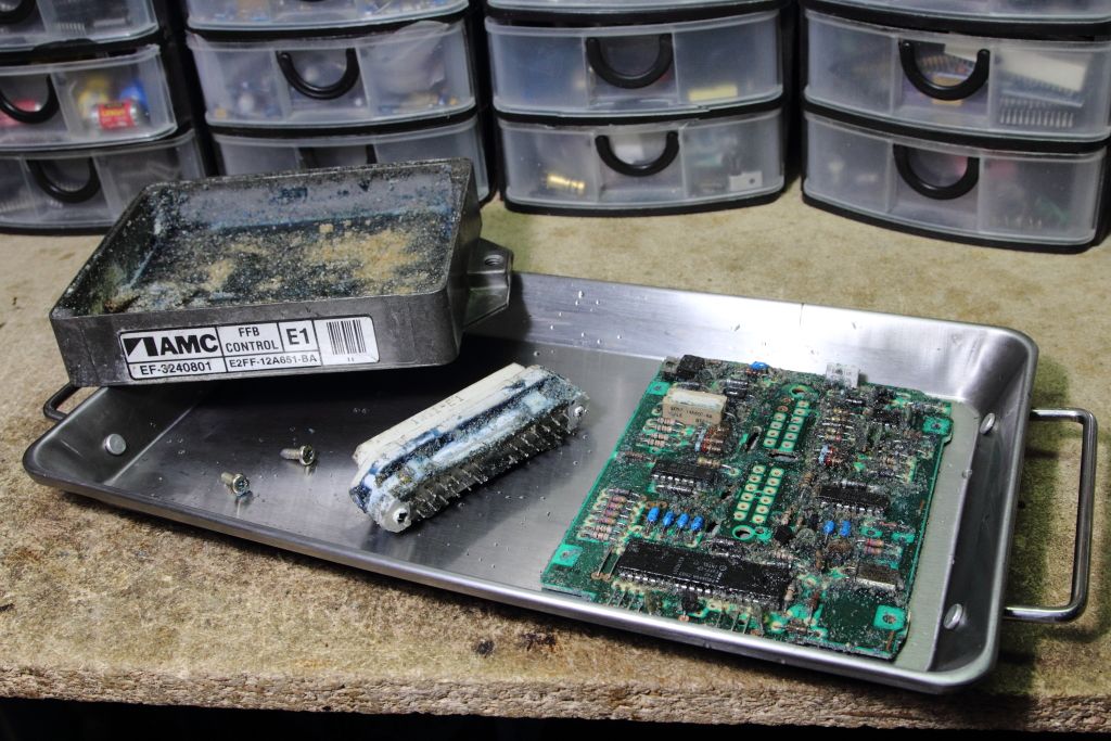
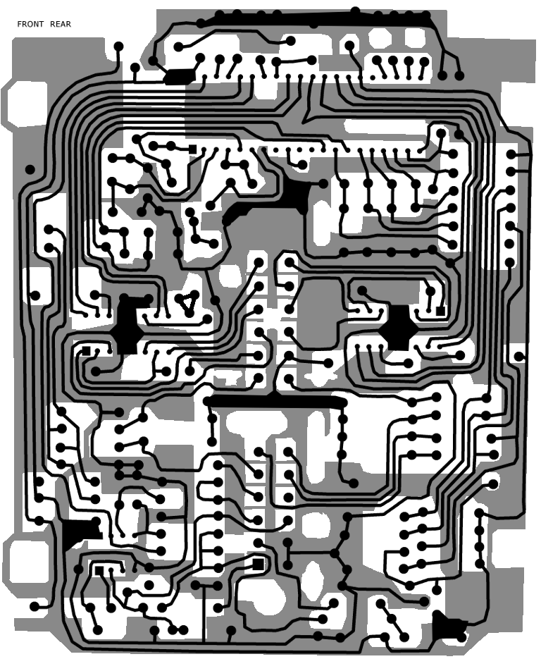
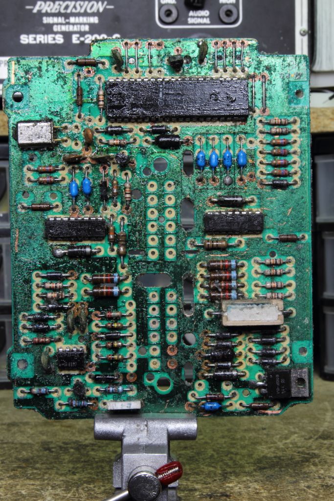
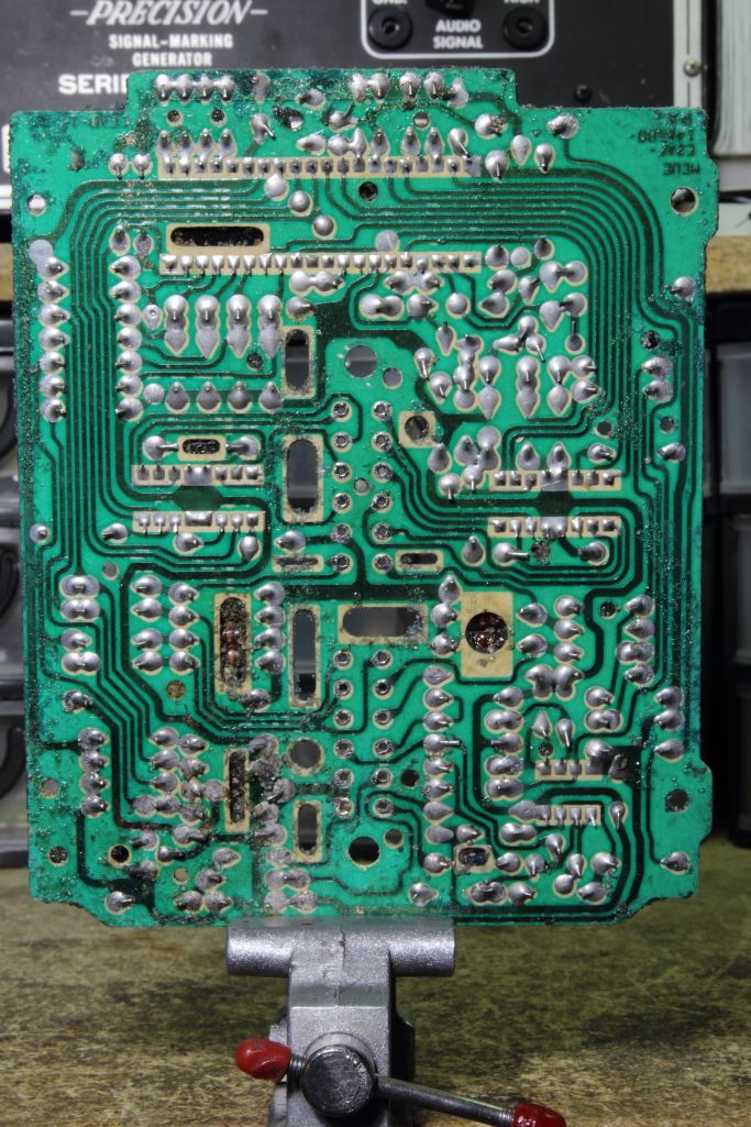
Below is the CeC in all its glory andfter a bit more cleaning up. As we can see the microcontroller dominates the top of the PCB while on either side of the connector there are two National Semiconductor drivers which I have yet to locate datasheets for. /B122 D9AF-DA If you look at the diagram above you will notice that lines form both of these chips go to the harness but are unused. Interesting. The only other IC is a Signetics that likewise I have not yet deciphered. 519 AF-CA 8137
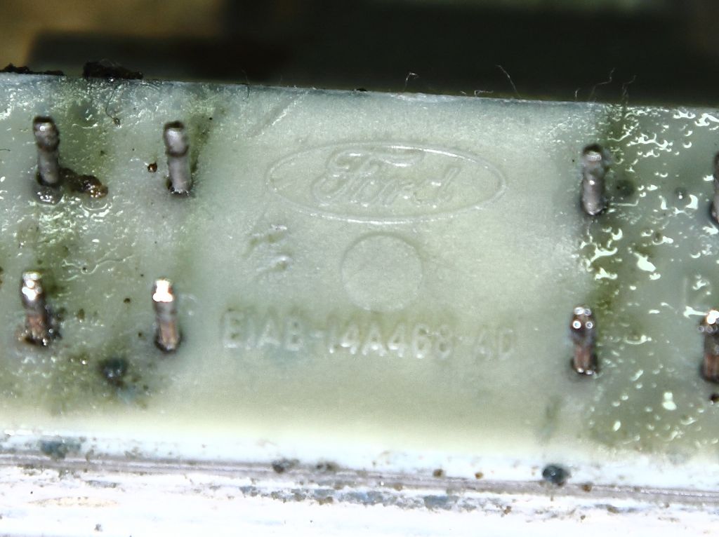
The connector itself is a peculiar Ford part. The logo is stamped underneath. This might be the most difficult component to find a replacement for.
Overall the CeC is what I expected. A low-cost microcontroller with very little else to help keep costs down. The CeC underwent at least four revisions over its lifetime. The original unit offered the handy CHECK ENGINE light, but then that went away due to available process cycles when electric timing retard and the Pulse Air injection was added. In 1983 the CeC was updated again to a new style called the C4 system which used a new microcontroller (the MCS-51?) and was then again updated not long after. All the while the Eagle remained a carbureted vehicle.
I still have a long way to go before I will have a modern replacement ready but this was a good first few steps thanks to a lot of luck. Next comes dumping the mask ROM of the microcontroller itself. One method is the 8049 Spy however the trusty old Willem supports reading and programming (refer to this schematic and these PCB files), so it may be easier to just make their adapter, pull it off the CeC and dump it that way.
Basically in that period the ability to run an engine loud and rich was being clamped down on to deal with smog and fuel shortages. Initially it was devices such as anemic carburetors, smog pumps, the Exhaust Gas Recirculation Valve and pellet-type catalytic converters which either by design or their primitive nature restricted how well an engine could perform and gave themselves a really bad reputation for neutering a car's performance (while everyone else who was not a full-time automotive person didn't really care) but by the 80's the computer was starting to become more common in the automobile and while affordable fuel injection was still another half a decade away some people pushed on and tried to figure out what they could do to make the carburetor as efficient as you possibly could.
American Motors, the same company who brought you Jeep until Chrysler bought them outright and surgically killed everything but the Jeep brand off could not afford fuel injection R&D time. Instead they decided to develop a peculiar system as had other car manufacturers around the same time where the amount of fuel atomized by the carburetor was more precisely controlled electronically. Their electronic fuel feedback system was known as the Computerized Engine Control and consisted mainly of on and off sensors that monitored the engine and carburetor for various static states which in tandem with an O2 sensor located in the exhaust manifold would drive a two-phase stepper motor in the back of the carburetor to control how rich or lean the mixture leaving the carburetor was, plus later on additional control for ignition retard and various smog control components.

Now of course like with the people mentioned at the beginning of this article there are quite a few in the older automotive world who have no comprehension how a computer can help a car, much less how to repair it when things go sideways, which they will do, when you attempt to adjust your idle jets and you are unaware that each screw turn is being countered by the computer until the computer can't compensate anymore and now you're mad that your car runs like total crap. This is why half-baked procedures such as the Nutter Bypass exist so you can either run high-performance replacement parts in the fuel and ignition system or better peace of mind because "HOW DARE YOU LET A COMPUTER DO THE LORDS WORK IN A CARBURETOR! >:U" Carters' 2BBD units from the same period and attached to the same CeC system were just as willfully disrespected. Over the years it is likely many a carb has been swapped out either because of the above or because kitchen table carb rebuild generally result in poor results. Do it right, people. Admit when you are in over your head and have a shop do it if it comes down to it.
Anyways, when I purchased a 1982 AMC Eagle wagon it too was equipped with a 6-cylinder CeC system. Being more tech savvy than automotive this was one of the first parts of the vehicle to be serviced. Indeed much of it is digital on/off, with the exception of the O2 sensor. It's stupid simple. My money is on the Speeduino shields out there being just that much more advanced than we would ever need to make a 1:1 CeC replacement.
While I was able to confirm that it still could do its job well with a new O2 sensor I still had many questions regarding the computer itself. In an Eagle wagon this exists by the feet of your passenger behind a panel. While modern ECU's have nicely gasketed covers and a light conformal coating it was decided by AMC and ironically Ford who manufactured the computer to instead screw the board to the bottom of a die cast pan and fill it with blue dyed silica mixed epoxy.

If I wanted to even start on the foundation towards making a modern replacement (pretty much functionally identical but the added ability to vary your "optimal" mixture and ignition retard which were both hard-coded on the original CeC) I would have to extract the board from its entombment. Normally removing potting is hard, due to the nature of potting compounds, however as I had observed with the Mastervoice ECU you can have potting batches that do not behave as they should and on the above donated computer the same now applied as the hard resin had begun to break down unto a rubbery but still softer material. This made it prime for boiling.
This is a depotting method that I have seen used before. Most epoxies at different temperatures will soften before more delicate components like large honkin' plastic harness connectors, or the IC's themselves.
In this case the computer was put in a stock pot filled with water and left on the stove for half an hour to cook.

When it came out of the pot it was of course scalding hot to the touch but with merely a screwdriver the epoxy could be scooped out in large chunks. Almost immediately I was able to identify the heart of the CeC, an automotive-grade Intel 8049. The MCS-48 series was Intel's first microcontroller and remained IMMENSELY popular unto the 21st century.

Continuing deeper found more components of the lone circuit board, then as I began digging out around the sides of the board I realized there was four unused screw holes. It turns out that to save a few pennies they left those out and instead two torx heads live in the harness connector. That way the board is still secured in place and the strain from the harness would not flex the board. Once those were located and removed the module was reheated and then using a heat gun on one side the board was carefully pried up and out.


Now that I had the board released I paid attention to how the harness connector attached to the two-layer circuit board. If I wanted to better clean the board up it needed to be removed. At this point I want to point out that hot air rework tools like the Hakko 850 and its various clones work great for heating up and picking out smaller lumps of potting while still giving you the control necessary to not melt and burn nearby components. Once that was out of the way the connector was easily desoldered and pulled.

Below is the CeC in all its glory andfter a bit more cleaning up. As we can see the microcontroller dominates the top of the PCB while on either side of the connector there are two National Semiconductor drivers which I have yet to locate datasheets for. /B122 D9AF-DA If you look at the diagram above you will notice that lines form both of these chips go to the harness but are unused. Interesting. The only other IC is a Signetics that likewise I have not yet deciphered. 519 AF-CA 8137


The connector itself is a peculiar Ford part. The logo is stamped underneath. This might be the most difficult component to find a replacement for.

Overall the CeC is what I expected. A low-cost microcontroller with very little else to help keep costs down. The CeC underwent at least four revisions over its lifetime. The original unit offered the handy CHECK ENGINE light, but then that went away due to available process cycles when electric timing retard and the Pulse Air injection was added. In 1983 the CeC was updated again to a new style called the C4 system which used a new microcontroller (the MCS-51?) and was then again updated not long after. All the while the Eagle remained a carbureted vehicle.
I still have a long way to go before I will have a modern replacement ready but this was a good first few steps thanks to a lot of luck. Next comes dumping the mask ROM of the microcontroller itself. One method is the 8049 Spy however the trusty old Willem supports reading and programming (refer to this schematic and these PCB files), so it may be easier to just make their adapter, pull it off the CeC and dump it that way.

