Steve Toner
Experienced Member
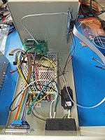
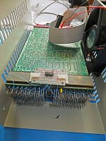
PDP-11 Qbus cards are plentiful and affordable, but you still need a backplane, power supply (that supplies a Line Time Clock signal) and enclosure which are somewhat harder to come by. I picked up a chunk of an old DEC backplane from the free table at VCF West. Don't know what it originally came from, but it had wirewrap pins and a PC board interconnecting them in a non-Qbus fashion. By cutting a few traces and wrapping some new wires, I was able to turn it into a 4-slot Q22 backplane:
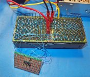
Note that +5V (red wire) and GND (black wires) buses were already provided. The yellow wire is +12V, and the little busboard is for front panel connection. The pin marked with a white heat shrink is for BPOK H, which DEC did not put on the ribbon cable.
So now I've put together a minimal 11/23 system with these boards:
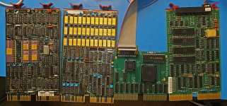
(L-R: M8186 with KEF11-AA floating point chip, M8059 RAM, RLV12 Emulator designed by Peter Schranz, M8043 serial card). The RLV12 emulator provides a virtual boot ROM. Otherwise, a crippled (RAM disabled) M8047 might have replaced the M8043...
I still need to put it in a case with a cooling fan, but for now I'm just testing it all splayed out on the workbench:
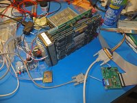
The blue board with the buttons and LEDs is the front panel - same as I used in my 11/53 build. It uses a PIC16F1615 to generate the power sequencing signals. LTC is generated with an optoisolator and can be seen enshrouded in heat shrink tubing to the upper right of the front panel board.
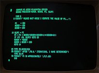
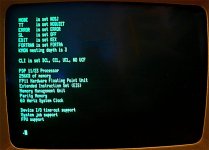
Running RT-11 (XM monitor):

Note that +5V (red wire) and GND (black wires) buses were already provided. The yellow wire is +12V, and the little busboard is for front panel connection. The pin marked with a white heat shrink is for BPOK H, which DEC did not put on the ribbon cable.
So now I've put together a minimal 11/23 system with these boards:

(L-R: M8186 with KEF11-AA floating point chip, M8059 RAM, RLV12 Emulator designed by Peter Schranz, M8043 serial card). The RLV12 emulator provides a virtual boot ROM. Otherwise, a crippled (RAM disabled) M8047 might have replaced the M8043...
I still need to put it in a case with a cooling fan, but for now I'm just testing it all splayed out on the workbench:

The blue board with the buttons and LEDs is the front panel - same as I used in my 11/53 build. It uses a PIC16F1615 to generate the power sequencing signals. LTC is generated with an optoisolator and can be seen enshrouded in heat shrink tubing to the upper right of the front panel board.
Running RT-11 (XM monitor):


