• Please review our updated Terms and Rules here

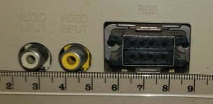
EIAJ RGB monitor connector

icono

Member
Joined
Nov 26, 2012
Messages
29
Location
Oklahoma, USA
I have a favor to ask of anyone that has an EIAJ 8 or E8M cable. Would you be able to measure the diameter of the pins on the male connector? I found a data sheet that all of the other plug measurements and I think I can design a 3d printable version of the connector. The only dimension I'm missing is for the pins.

It will be for the RGB Jack20230911_212117~2.jpg
 
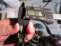
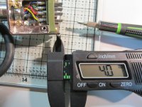
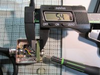
Good idea! I started making a PCB version of this connector (stack two PCBs to provide the "base" for the connector,) but got tripped up trying to panelize it for JLCPCB. My friend measured his connector for me, and said the pin diameter was 1.50mm and roughly 6.75mm deep into the connector housing.

I wasn't able to find a good crimp pin to use for the inserts, but I also got discouraged with the panelization problem. Please let me know if you'd like my kicad files.
 
The pin is what I have been struggling with the most. I have ben thinking of making my own solder pins.

15 gauge wire is 1.45 mm
1/16 inch brass rod is 1.57 mm
 
I was able to find 1/16 in(1.588mm) brass rod at my local hardware store. I was going to try "turning it" using a drill and some "precision files" I got from harbor freight. The rod was $2.50 for 3 feet so I should be able to make plenty of mistakes.
They also had 1/32(0.794) bass rod.

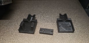
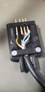
The connector is coming along nicely my first few prints the tolerance was too tight. I've adjusted the tolerance and have another one printing now. It's being designed to be used with a cut down VGA cable. The ferrite from the cable can be held in the cylinder at the top to act a strain relief. The other end of the VGA cable would replaced with whatever connector would be needed.
20230924_124028.jpg
 
Last edited:
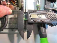
The pin length from plastic housing are about 6mm.
IMG_3953.JPG
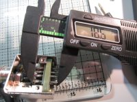
The pins are about 18.5 total through the housing.
IMG_3954.JPG

The little ledge is about 4mm.
IMG_3956.JPG
The plastic plate is about 5.5mm.
IMG_3957.JPG
 
Turns out grabbing the ferrite is a little harder than I though it would would be. All of my VGA cable seem to have different size Ferrites (older ones seem bigger newer ones smaller).
1. I could try resigning it with a cable clamp like the original connecter does but that would mean it needs 6 screws.
2. I could try to design a little spacer that fits in the cylinder of my current design and grabs the cable(it would take a different spacer for each cable size)
 
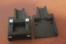
I decided to go for a cable clamp. Here is my latest design. It will end up using 6 #4 3/8 Flat Head Screws. I was able to find "uxcell 0.3mm x 0.9mm x 500mm Brass Pipe Tube Round Bar Rod" on amazon for $5.99 should be able to use it to make my own solder pins. I should have it tomorrow but it will take me until next week to have enough time to work on it.
20231003_203748.jpg
 
Great progress. Then again, you could always open up the monitor and replace the EIAJ with the more common DE-9 socket, saving yourself all the connector hassle. Period-correct religion set aside as you already went crafting the enclosure on a 3D printer anyway.
 
Great progress. Then again, you could always open up the monitor and replace the EIAJ with the more common DE-9 socket, saving yourself all the connector hassle. Period-correct religion set aside as you already went crafting the enclosure on a 3D printer anyway.

Sears rebranded the monitor from another OEM(I can't remember who the FCC ID comes back to) . They sold adapter cables for different computers. I plan on using it for my Laser 128 EX that uses a 15 pin DSub for the video connector.

*Edit I just looked it up again and The FCCID AFA9YBR3CL comes back to Sanyo. The connector is PCB mounted the footprint for a DB9 and the EIAJ don't line up. I'm not sure of a good way to do a socket swap.
 
Last edited:
The connecter appears to be able to accept a wide range of pin and still have a snug fit. 0.9mm is way to small. I was able to make my own pins(with very poor quality control) they range from 1.5mm to 1.36mm most are in the 1.45mm range. The pin that's 1.5mm is a little tight the 1.36mm pin still seems to fit well.
 
Success!! I was able the make the connector and solder up a cable and now I have RGBI video on my Laser 128EX!

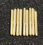
I made the pins by cutting a 20mm section on 1/16 in brass rod. The I put the small piece in a cordless drill and spun it while filling. I filled it down to 1.5mm - 1.36 mm. Only 7 of the 8 pins are used.

20231007_005658.jpg

I had to make the connector slightly longer to fit the pins.

20231006_111721.jpg

I need to make a few tweaks to the design and I will release the STL and the CAD file for free
 
Last edited:
Back
Top