• Please review our updated Terms and Rules here

Epson PX-8

shan2752

Member
Joined
Nov 26, 2017
Messages
41
Location
Ohio, USA
Hi,

I just sourced 5 Epson PX-8’s boxed. Some of the software has never been opened. I’m planning on keeping one but would like to make the other 4 available to others. Is it better to offer all 4 or should I offer 1 at a time? Also what do you think a fair price would be either separately all for all 4? They appear to be in very good condition. Any information would be greatly appreciated. If they are valuable I want to split what I receive with the 90 year old owner who was clearing out his old IT business building in a historic downtown.

He also gave me an Epson HX-20. Thanks!
 
I would say they go for around $200 for the unit, more depending on what you have that goes with it. If you happen to have one of the floppy drives, you can get $200 for just it (maybe more).
 
I got mine in the middle of last year for £72 in the UK; this including computer, SSD, floppy drive, acoustic coupler, manuals, printer, and shrinkwrapped box of software what I don't know what it is. All works, too. Not that I'm smug or anything...

I haven't made videos about them all yet, but I did make this film of the printer:

https://www.youtube.com/watch?v=2Vf8Zvz1kDs

BTW, all PX-8 components contain 4.8V internal nicads that need to be pulled. I haven't done mine yet and I should really do it ASAP. The PX-8 is kinda weird and you typically can't run the various bits off the AC supply (they frequently draw more current than the AC supply can supply), and I've had better luck just connecting 5V to the battery terminals directly. I was thinking of removing the internal batteries completely and patching them to the main battery terminals instead; I don't want really want batteries inside the case at all.
 
I watched your video on FluxEngine and I think it's a great little project. We need something like that to replace our "tweener" PCs commonly used to copy files and boot disks from CP/M machines. My tweener is dying at the moment so i'm looking for an alternative. Are you familiar with cpmtools? Porting that to use FluxEngine would be a great thing to do...
 
Thanks! (I just got emailed by a different Jon, BTW --- is that you?) cpmtools works fine on the images FluxEngine produces, by the way.

...and this is on topic, because it reads PX-8 disks! Which are 3.5" 40 track IBM scheme MFM disks. Writing one will be a challenge on an 80-track drive. I'm hoping that blanking (erasing but not writing data) every other track will do the trick.

I performed the batteryectomy, by the way, removing the internal battery. Two of the four tiny NiCd cells were obviously toast, but had luckily not leaked. Instead I wired the internal battery connectors to the handy GND and VB+ posts on the motherboard so that applying power to the main battery terminals drives them both. The cassette drive is enormously power hungry and at 5V would frequently brown out the machine when doing tape operations (screen goes blank and CHARGE BATTERY appears). Raising the voltage to 5.4V fixed that, which the technical manual says is safe, but the screen still flickers when the motor starts or stops. Now that the machine's zipped up again I belatedly realise that a big capacitor in the battery bay would probably have been a better solution.
 
Sadly my batteryectomy of the PF-10 floppy disk drive didn't go so well. I managed to make the second-most common newbie mistake and hooked it up to 12V instead of 5V. Annoyingly, if I'd made the most common newbie mistake and connected it up backwards it would have been fine as all this stuff is diode protected...

The internal 2A fuse has blown, and after bypassing it it no longer responds to commands from the laptop. There's a schematic at http://electrickery.xs4all.nl/comp/px8/doc/f10pa.pdf and I spent some time following the power supply circuitry. The +12V and +5V supplies are both generating sensible voltages but the -12V supply is showing about -7.8V, so I reckon something's fried there. The -12V module is fairly self contained and is powered from VRS, which is showing a sensible +5V, so that pins down at least some of the damage. (See logic sheet 3 of the schematic). Luckily the serial port on the PX-8 is still fine.

I'll admit to being completely out of my depth trying to diagnose this. I'm can't tell how that circuit works --- if it's a negative charge pump, shouldn't there be an inductor? --- so I can't tell what's wrong. I also very much doubt that's the only damage. The CPU is getting 5V, and isn't responding to serial commands, so either it hasn't come out of reset because it's waiting for the -12V line to settle, is damaged, or the serial drivers have asplode. Also I can't find anything in the schematics which use that -12V line. Hand drawn schematic, not searchable...

Any suggestions?
 
The CPU is being clocked, it's not in reset, but the address and data lines show no activity. I reckon it's dead, and I'm probably not up to replacing it, even if I could find one.

Anyone got a spare main board for a PF-10 that they don't want?
 
hjalfi,
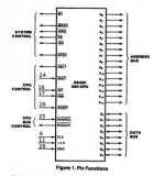
There are a few more INPUTS to the Z80 that can be verified. (ALL are Active LOW).

CPU BUS CONTROL
Pin 25 - INPUT - BUSREQ

CPU CONTROL
Pin 16 - INPUT - INT
Pin 17 - INPUT - NMI
Pin 24 - INPUT - WAIT
Pin 26 - INPUT - RESET


Larry

z80-1.jpg
 
Last edited:
The PX-8 itself is fine, thankfully; it's just the PF-10 floppy drive which is dead.

I've spent some time tracing lines with the oscilloscope and the schematic (which is amazing and invaluable). It's possible the CPU is actually in low power sleep waiting for an interrupt. The schematic shows that the only interrupt source is a line derived from /RS232On, which is CPU controlled. Said line is not connected to the RS232 circuitry at all, at least according to the schematic.

More lines to probe, I suppose; also the internal E clock from the CPU is exposed via a test pad, so I should check that with the scope too.

I have a logic probe and logic analyser on order.
 
Good news! It's alive. That -12V line? The schematic is wrong and it's supposed to be -7.8V. The CPU is alive and on the scope I can see it wake up and do stuff when I send it serial bytes.

I have yet to see it send stuff back, but I suspect that's because I'm not giving it the right EPSP commands --- the protocol's more complex than it looks (I found it here: https://fjkraan.home.xs4all.nl/comp/hx20/epsp.html Also, I've never seen anyone actually use the ACK/NAK/EOT/SOH etc ASCII bytes before!)

Are there any tools which will allow a PC to talk to a PF-10? I've found several that will let a PC emulate a PF-10, but that's not what I want.
 
Status update: I am not seeing any response to the commands I send it. I'm relatively sure that I've got the protocol right, and I'm not receiving any kind of ACK/NAK from the drive. Probing the internal lines with a scope shows that there's not only no activity on the external serial port but that there's no activity between the CPU and the 75188 line driver.

So, one of the following must be true:

- the CPU is deliberately not sending a response (for whatever reason).
- the CPU's Tx driver is blown.
- the 75188 Tx driver is blown and the CPU's Tx line is tied high.

I'm hoping it's the last, as that's the easiest to fix. A new 75188 will cost me nothing plus quite a lot for shipping, and it's an easy-to-work-with PDIP, so I might just replace it on spec to rule out the third option. It does make sense that the 75188 is dead, as it takes both +12V and -8V and so it's plausible that it'd take the brunt of the voltage spike before the fuse blew.

Identifying the others... well, I have a logic analyser on order. With that I'll be able to log the ROM bus activity. That'll tell me what code it's running and so I'll be able to figure out precisely what the CPU is trying to do. If the CPU Tx driver is dead (why?) then the only recourse would be to replace the CPU, and it's a SMD QFP package which looks nightmarish to get off. Simply sourcing a replacement looks terrible; the only vendors I've found are on places like alibaba, and I'm very suspicious that they just happen to have a stock of HD63A03XF processors in a warehouse somewhere and not, say, a chunk of resin with a poorly printed label.

It does look like most of the PCB is good, though. The drive circuitry is powered on in software, so it wouldn't actually have been powered up. This may actually be repairable.
 
Remember this? I'm still working on it! I now have a pile of (cheap and nasty) tools, including a logic analyser.

So far I have:

- replaced the gross physical damage, including replacing the soldered in fuse with an actual fuse holder (containing fuse)
- replaced the serial tx and rx chips, just in case the problem was the easy-to-replace tx chip, and it's not.
- verified with logic probe that the processor is thinking about each incoming serial packet. I knew this before, but it's nice to verify.
- snooped the data and address lines with the signal analyser, and I can see the processor waking up from an interrupt, pushing its registers onto the stack, doing stuff, and going back to sleep again.
- attempted to map what I'm seeing to the ROM dump from https://fjkraan.home.xs4all.nl/comp/px8/pf10/, and failed... did you know that there are several different versions of PF10 firmware? Mine's a K4, and the one I have the dump for is a K3.

My current hypotheses are, in increasing order of hard-to-fix: (a) my test program is simply sending malformed packets and I'm not seeing a response because they're junk; (b) some non-surface-mount component is dead, and I'm not seeing a response because the PF10 hasn't initialised yet; (c) the processor's output UART is fried. Verifying what it's doing with the logic analyzer will definitely pin this down.

The logic analyser (a cheap and nasty 8-port fx2lafw model) is a great success but it's only got eight lines, so I can't see the address bus and data bus at the same time. My plan was to watch the bottom byte of the address line and correlate with a dissassembly to figure out what it's doing, but my disassembly doesn't match the ROM so I can't do this. So, my next step is to dump the ROM, which involves finding someone with an EPROM programmer I can borrow. This may be hard.

...don't suppose anyone happens to have a K4PF10 ROM dump anywhere?
 
Why not test it with the PX-8 again since it knows the right protocol to use? The protocol is somewhat of a pain, but a few people have coded it. I am working on a TF15 emulator that will use microsd, but still trying to get time to finish the firmware before I try to build a pcb for it. I keep trying to win a PF-10 on eBay, but they are few and when they show up the price goes way too high for my liking.
 
I dumped the ROM --- it's attached if anyone's interested.

This let me use the logic analyser to trace the code. When a data byte arrives on the serial port, the CPU is waking up, and I can watch it service the interrupt (which just resets some flags) and then attempt to read a byte from the UART RX register: but this byte looks like it's always 0xFF. (Although it's possible that reading from an internal peripheral register doesn't express the value onto the external data bus.)

So, my current hypothesis is that the UART on the CPU is fried, with just enough logic remains to trigger an interrupt when activity occurs, but the actual shift register itself is non-functional. That puts me right back at my earliest worst-case scenario where I need to replace the CPU.

I suppose the next step is to get hold of an EEPROM or ROM simulator and try writing my own code for the thing, I suppose, to verify this for sure. On the upside, the 6303 is a pretty interesting architecture...
 

Attachments

  • k4pf1.zip
    2.7 KB · Views: 2
Crazy thought: assuming the rest of the CPU's fine (the actual CPU bit works, but I don't know about the peripherals), I could patch in my own UART via the exposed address and data lines in the EPROM socket, and then modify the code to use that instead of the built-in peripheral. That'd save having to solder surface mount FP80 packages, and more importantly, desolder them first...
 
Back
Top