• Please review our updated Terms and Rules here

Five Festive 5150 Boards (BOARD #1 Thread)

VeryVon

Miner 2049'er
Staff member
Joined
Oct 21, 2021
Messages
326
Location
Land of the Cheesesteak
Welcome to Board #1!

[Link to Original Thread / Board #3]

Here's what I know so far:
- Motherboard type 64KB-256KB
- Known good CPU inserted
- Known good RAM populated in Bank0, other banks unpopulated
- RDR Doesn't boot up, no beep, LPT says "00" and nothing more
- Booting with known good BIOS, no beep, no video
- Verified power supply
- Verified 4.77 MHz clock
- No pulses on pin 13 of the 8253 chip

Performed The 'ground I/O CH RDY' Procedure, this is what I see:

8088's READY (22) and RESET (21) pins are LOW
A0 H
A1 H
A2 H
A3 H
A4 H
A5 H
A6 H
A7 H
A8 H
A9 -
A10 L
A11 L
A12 H
A13 -
A14 -
A15 -
A16 H
A17 H
A18 H
A19 H

Where '-' appears to be high impedance (logic probe is silent)
 
Last edited:
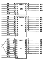
That will be step 4 that you are referring to, where HHHHHHHHHHHHLLLL (address FFFF0) is expected on the address bus.

Your measurement shows 10 of those 20 lines not being as expected.

Reference diagram at [here].

In reading step 4 of the procedure, you are sure to have read the note in step 4.

The bits on the address bus that you are measuring not as expected, are not confined to the range of A0-A7, or to the range of A8-A15, or to the range of A16-A19.
If they were in fact confined to the A0-A7 range, then I would be suggesting that you replace U7.
If they were in fact confined to the A8-A15 range, then I would be suggesting that you replace U9.
If they were in fact confined to the A16-A19 range, then I would be suggesting that you replace U10.

Maybe both U7 and U9 are faulty, but there are some other checks that can be done.

Line A13

The fact that some of the lines are neither HIGH nor LOW is relevant. Take for example, A13. Line A13 is driven by U9. And in the 'ground I/O CH RDY' procedure, expected is that U9's /OE pin (pin 1) to be LOW, resulting in U9 driving either a LOW or HIGH onto the A13 line. Is U9's /OE pin at LOW ?

If it is LOW, then I suggest that you replace U9, and then see if the range of A8 to A15 becomes as expected.

If it is HIGH, then we need to work through the circuitry to see why U9's /OE pin is not at LOW.


1705787429159.png
 
Ok indeed, U9-1 is HIGH. I'm having a look at the schematics as well, seems that AEN BRD is driven by U98?
Well, driven by U98.

- Faulty U98 ?
- Good U98, but a bad input to U98 ?
- Faulty 8288, stopping the AEN BRD line from being driven LOW ?
- Another PCB problem ?
 
Add:
- Faulty U84, stopping the AEN BRD line from being driven LOW ?
- Faulty U97, stopping the AEN BRD line from being driven LOW ?
 
Add:
- Faulty U13, stopping the AEN BRD line from being driven LOW ?
- Faulty U15, stopping the AEN BRD line from being driven LOW ?
- Faulty U16, stopping the AEN BRD line from being driven LOW ?
 
Correct yes, and I'm checking U98, I see U98-4 is HIGH which I believe would make U98-2 (AEN BRD) HIGH.

p.s. U98-1 (CLEAR) is also HIGH, U98-9 (CLOCK) is good.
 
Ok, I'm suspecting there's an issue with U67, because it has 4.7 MHz on Pin's 2 & 3, CLR is High, but PR (tied to /Q) is always LOW.
 
Ok, I'm suspecting there's an issue with U67, because it has 4.7 MHz on Pin's 2 & 3, CLR is High, but PR (tied to /Q) is always LOW.
Using the procedure on my good motherboard, the CLR pin is LOW.

Working back from there: U52 pin 3 is LOW and pin 2 (i.e. /HRQ DMA) is HIGH.

Working back from there: U99 pin 2 is HIGH, and pin 1 is LOW.

Working back from there: 8237A pin 10 is LOW.
 
Where '-' appears to be high impedance (logic probe is silent)
All you can really say about those measurements is that the line is neither HIGH nor LOW. The driving chip having its output line in high impedance state is one possibility.

But a consideration is the possibility of two chips in a HIGH/LOW 'tug-of-war', with neither winning, resulting in the line voltage being in the 'neither HIGH nor LOW' region.

And related to this, in your Introxic LogicPort LA's software, you will not find a TTL/CMOS setting. What there is, is a 'Logic Threshold' setting, which is set to a single voltage level. And so in your captures, you will not see the state of 'neither HIGH nor LOW'. It is something that I always keep deep in the back of my mind during investigation using my LA.
 
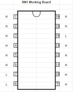
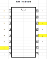
Some observations on RN1 - Working board vs. this one:

1705800696934.png1705800788203.png

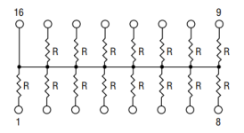
According the the parts list, RN1 is a 15 resistor bussed network

1705800587285.png
 

Attachments

  • RN1 Datasheet.pdf
    212.8 KB · Views: 0
Last edited:
Well easy decision which one because RN1-12 is too close to SW1 to be snipped, so I snipped U52-1, and... RN1-12 is high now, U52-1 (disconnected) low, so I'll pull it.
 
Pretty soon, you'll be able to add this skill to your resume
Thank you, yes!

Ok some progress. The speaker is now making the nice "click" that it should (before it was just making fuzz)

And we've fixed those pesky first four bits (A0-A3) the rest remain unchanged. U9-1 is now enabled low.

A0 L <- fixed
A1 L<- fixed
A2 L<- fixed
A3 L<- fixed
-no change below here-
A4 H
A5 H
A6 H
A7 H
A8 H
A9 -
A10 L
A11 L
A12 H
A13 -
A14 -
A15 -
A16 H
A17 H
A18 H
A19 H
 
Back
Top