• Please review our updated Terms and Rules here

Golden Star 8088 and two 5150 boards

SpidersWeb

Veteran Member
Joined
Feb 16, 2012
Messages
2,701
Location
New Zealand
After setting myself up a new workbench with lots of room (plus a few new tools) I decided to have a crack at these three motherboards.
These are motherboards I've attempted to investigate earlier, but got put in the 'too hard, deal with it later' box.

None of these are absolutely critical parts - they're really spares - but I'm enjoying a little bit of practical diagnostics and it's good for learning, but without a win I wanted to come on here and get some advice.

<removed references to other two boards to avoid confusion>

Golden Star Turbo Plus (C) 1986 board 3:

Came inside a random case as non-working, it appears to have lost its mind.

IMG_0309_zps9ytvnvzy.jpg


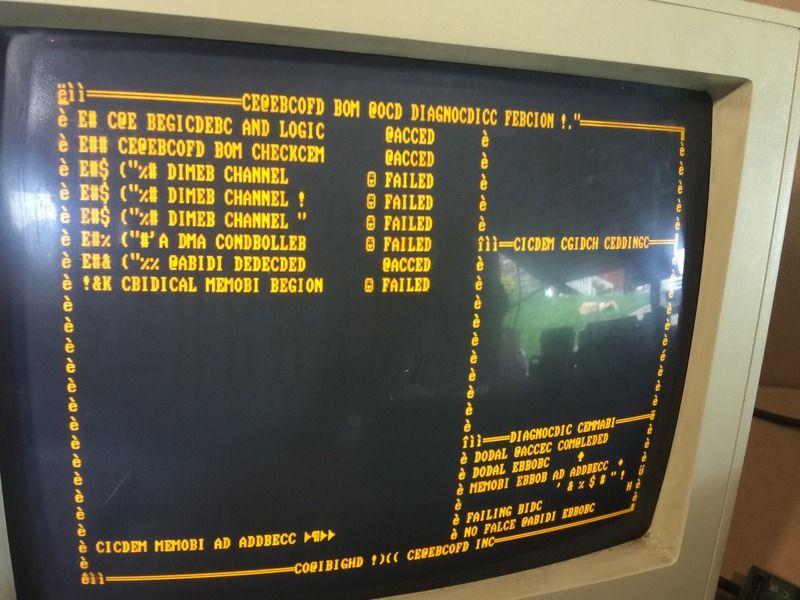
So one or more data bits aren't getting to the video card, causing lower ASCII values. I tested for continuity between D0 -> D7 on the ISA bus to a 74LS245 chip which is an octal buffer for the CPU (right next to the CPU and first ISA slot). I then checked the continuity between it's inputs and the CPU. All connections were 100%.

I then used a logic probe to check for signal activity on D0->D7 on the ISA card - all seemed to be firing busily.

I then tried replacing the CPU - no change.

Any suggestions on what to do next?
 
Last edited:
Golden Star pictures
IMG_0313.jpgIMG_0320.jpgIMG_0323.jpgIMG_0324.jpg

NB: Original CPU was a Fujitsu 8088-2, photo is of it's replacement. No change with switching.
 
My first guess is the onboard MDA SRAM. @->P means that 40H->50H; C>S, similarly 43H->53H... means that bit 4 is getting dropped from the screen SRAM on the video adapter.
 
Putting multiple items into one thread is a bad idea.
There is a tendency for people (like me) to get confused.
And if people do not quote, then there is the "Which board is this a response to?"
 
IBM 5150 board A

IBM 5150 board A

IBM 5150 board A)
64-256 model. Originally purchased in working condition off ebay, very clean, nothing looks worn or even dirty, have reseated and swapped processors - no change.
Original ROM installed - RAS is held high, so it's not even getting to the 16KB Base Ram test
Diagnostic ROM installed - nothing happens
First, using an oscilloscope, I would check that the clock for the CPU is being generated. Because it is easy to do, I would probaby check all clocks (per [here]).

I would then use my logic analyser. When RESET is lifted, the CPU starts execution at address FFFF0h, which in the 5150 is an address in ROM (IBM BIOS ROM or SuperSoft diagnostic ROM). So I would monitor the ROM pins. Is the ROM being selected? The correct address being presented to it? The expected output bytes? The results then steer which way I would go.

That is what I would do. Others will differ.
 
IBM 5150 board B

IBM 5150 board B

IBM 5150 board B)
64-256 model. Arrived in a 5150 case base (no lid) as untested, no corrosion but very dirty, suspect it had a long life (someone installed a 140MB MFM, new PSU, twin 5.25, 384KB+RTC options etc)
Original ROM installed - healthy RAS signal found, no start
Diagnostic ROM installed:
- showed errors on bank 0, parity and bit 5, removed errors by piggybacking ICs - Base 16KB RAM test passes BUT:

On cold boots, it stops at the '8255 parity detected' test
The '8255 parity detected' test is described on "Page 20" of the manual for the SuperSoft/Lanmark diagnostics. Refer to the diagram [here]. So, before RAM refresh is started, the diagnostics are interrogating the 8255 as to the state of its PC6 and PC7 pins, both pins expected to be reflecting no parity errors.

... and I have to power cycle, after the power cycle it passes this test and then passes the base RAM 16KB - this failure is consistent, and as long as the power isn't left off for more than 5 seconds - will keep passing the test.
Sounds like a temperature sensitive symptom. Have you tried non-conductive freeze spray?

After it passes, it then fails "Memory Refresh", and also identifies Bit 2 is failing on slow refresh later.
Maybe you should rectify the 8255 related failure first, then see if this failure remains.
 
My first guess is the onboard MDA SRAM. @->P means that 40H->50H; C>S, similarly 43H->53H... means that bit 4 is getting dropped from the screen SRAM on the video adapter.

Video card was tested prior, but to double check I just installed a DTK MDA board from a Turbo clone - and the problem actually got slightly worse (I also tried multiple slots, and had consistent results).

IMG_0328.jpg

From what I can tell, it must be able to read data just fine, but sending out instructions it loses a bit or two - which could possibly also explain the failures for the timer / DMA tests.
 
First, using an oscilloscope, I would check that the clock for the CPU is being generated. Because it is easy to do, I would probaby check all clocks (per [here]).

I would then use my logic analyser. When RESET is lifted, the CPU starts execution at address FFFF0h, which in the 5150 is an address in ROM (IBM BIOS ROM or SuperSoft diagnostic ROM). So I would monitor the ROM pins. Is the ROM being selected? The correct address being presented to it? The expected output bytes? The results then steer which way I would go.

That is what I would do. Others will differ.

Thanks! Appreciate your time.

As per your earlier advice, I'll make another thread for the 5150 boards. The Golden Star is the one that's all hooked up at the moment so I may focus on this first, then return to the 5150's.
I do have a scope and logic analyser (although it's a cheap PC based model) so I'll give that a try and report back in a separate thread.
 
Looking at the PC bus diagram in the Sams "IBM PC Repair and Troubleshooting" guide I noticed the data bus is controlled by three 74LS245 ICs - being a clone I figured it probably has the same architecture. I found the outputs (figuratively speaking) connected to each other and the pins (D0 to D7) on the ISA slot. So I used the scope on the inputs and outputs - as I thought it might be me an indication. The wave forms were pretty poor, very long rise times (like a curve) then fast drop offs. I also noticed the signal seemed to look worse around bits 4 and 5 (my meter isn't the best, and I didn't write it down at the time as I was just messing around).

So the first thing I might try is replacing all 3 of the 245's. This may not be for a week or so, as I need the parts, and the time to fiddle around desoldering.

Keen to hear anybody elses ideas, or specific points on the board I can probe / check. I'm just trying to wing it here.
 
From the first screen it looks like it's trying to report something like:

- Timer channel failed
- DMA Controller failed
- Memory failed

And obviously some characters got messed up, like "R" is displayed as "B", "T" is displayed a "D" and so on.

Not gonna claim it's impossible that all of that is broken, buuuuuuuuuut - is it likely?

All of that together i guess the BIOS is corrupted. Hard to tell from here and just from some pictures and description, but that would be my first guess here...
 
Back
Top