• Please review our updated Terms and Rules here

[gridcase] Anyone made a pin-out sheet for the External Peripheral, and/or the P2A/P2B bus connectors behind the battery?

tschak909

Experienced Member
Joined
Mar 26, 2018
Messages
96
Location
Denton, TX USA
Just as the subject says:
The P2A/P2B connectors in the battery bay are a complete 16-bit ISA bus split into two connectors, has anyone attempted to tone out the pins and what they map to?
-Thom
 
Joined
May 5, 2022
Messages
40
I know they are for the ethernet cartridge, (unobtanium) but beyond that I don't know of anyone using them.
The pin outs are most likely on that pdf that you are seeking unfortunately.
 

tschak909

Experienced Member
Joined
Mar 26, 2018
Messages
96
Location
Denton, TX USA
I am aware of this. It's one of the reasons I am looking for the Technical Reference manual, as it has the pinout for these connectors, am wanting to do a version of the FujiNet that fits into the bay.

-Thom
 
Joined
Sep 26, 2020
Messages
31
Location
Belgium
Bump,
I'd also love to find the pinouts of either the Gridcase /Gridcase+ 50pin external bus connector, the 1537e expansion /HDD bay or the 15xx series expansion / battery bay pinout.
I'd love to make something similar to what I did for the Toshiba T-series (CF card + Adlib + ethernet) I've already attempted to trace out the 50 pin connector in my Gridcase Plus but gave up after a couple of hours going nowhere with the multi-layered boards. https://conventionalmemories.com/wiki_cm/3inONEder_for_Toshiba_portables
 

Dagwood

Experienced Member
Joined
Oct 16, 2018
Messages
65
I'd also love to find the pinouts of either the Gridcase /Gridcase+ 50pin external bus connector ... I've already attempted to trace out the 50 pin connector in my Gridcase Plus but gave up after a couple of hours going nowhere with the multi-layered boards.
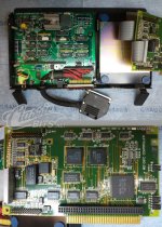
I'm not sure if this is any help or not but attached is a photo of an external 10MB hard drive that clamps to the top of my GRiDCase Plus and interfaces to the 50-pin connector. Inside is a PCB with an IDC header that appears to be an 8-bit ISA slot. There is an ISA card (Controller for the JVC hard drive) that has an ISA card edge connector but also the female IDC to match. I haven't examined it closely to determine what all the other stuff on the PCB is. Some of it is surely power related but there's logic there too. Additionally there is a pass through of the 50-pin which I would expect to be for daisy chaining except it's covered with a warning label saying not to use it.
 

Attachments

  • GridCase-50-Pin-Expansion-JVC-Hdd.jpg
    GridCase-50-Pin-Expansion-JVC-Hdd.jpg
    336.5 KB · Views: 9
Joined
Sep 26, 2020
Messages
31
Location
Belgium
It is documented in the Hardware Reference Manual, very end:
Ohh that's great, I didn't realize they were in there, guess I'll have to make a prototype adapter board then.
I'm not sure if this is any help or not but attached is a photo of an external 10MB hard drive that clamps to the top of my GRiDCase Plus and interfaces to the 50-pin connector. Inside is a PCB with an IDC header that appears to be an 8-bit ISA slot. There is an ISA card (Controller for the JVC hard drive) that has an ISA card edge connector but also the female IDC to match. I haven't examined it closely to determine what all the other stuff on the PCB is. Some of it is surely power related but there's logic there too. Additionally there is a pass through of the 50-pin which I would expect to be for daisy chaining except it's covered with a warning label saying not to use it.
Wow that's really cool. I see that the board is in labeled in French, is this from one of the SAGEM rebranded GRiDs?
Could you take a higher quality picture of the adapter board? It looks like just a bunch of logic IC's, as long as there aren't any PAL or GAL's it shouldn't be to hard to reverse engineer. Although I suppose that I'd have to get my hands on one of those to really be able to measure out everything.
 
Top