• Please review our updated Terms and Rules here

Having trouble connecting a gotek to my Osborne 1a to run software

BushmanBushman

New Member
Joined
Aug 16, 2023
Messages
6
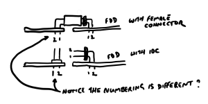
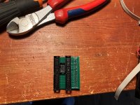
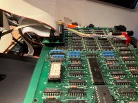
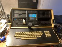
I have been having some issues attempting to install a gotek into my Osborne portable. So far I have attempted a couple of things but the computer always either reads out an error after starting to read the file or starts hanging the process without an error code. I'm not completely sure I have my gotek set up correctly and was wondering if anyone could send me their ff.cfg file or the correct jumper settings or anything I would need for my drive to recognize and be able to read from .hfe files. I'm not completely sure this is an issue specific to my hardware, as none of the disks that came with the computer either of the drives were able to read, but they still gave bad sector errors. It would be greatly appreciated. In case it is important, I have been trying to use the programs already prepared by Richard Loxley (https://www.richardloxley.com/2018/04/27/osborne-restoration-part-16-transferring-cpm-software/)
 
Hopefully you are aware that the O1 repurposes a bunch of the odd-numbered pins as power connections? Installation of a Gotek requires an adapter to avoid heartbreak.
 
Yes, I was already aware of this and made my own adapter before attempting to get the gotek working. I appreciate your concern though.
 
Heh. No one wants to be Captain Obvious, but vintage computer folks try to prevent other vintage computer folks from letting out the magic smoke.

Regarding your original issue, might be worth checking voltages and logic states at the Gotek end. Good luck!
 
These are the CFG files I use for the Gotek in my Osborne 1. The main difference is that I have an older, stock Osborne 1 (not a 1A which I came the double density upgrade... but I could be wrong about that.), so these settings are for the single density drives. Although I think the 1A should at least be able to boot those. There is a SSSD bootdisk image in there aswell.

EDIT:
Also, as per this thread somewhere else: https://comp.os.cpm.narkive.com/dPFZxnAY/gotek-success-anyone

SSSD IMG.CFG

# Osborne 1: SSSD, 40 cyl
[::102400]
cyls = 40
heads = 1
interleave = 2
secs = 10
mode = fm
rate = 250
bps = 128
id = 1

SSDD IMG.CFG

[osb2]
cyls = 40
heads = 1
secs = 5
interleave = 1
bps = 1024
id = 1
#rpm = 360
rpm = 300
rate = 250
mode = mfm
iam = no
 

Attachments

  • GotekFiles.zip
    91.2 KB · Views: 4
Last edited:
These are the CFG files I use for the Gotek in my Osborne 1. The main difference is that I have an older, stock Osborne 1 (not a 1A which I came the double density upgrade... but I could be wrong about that.), so these settings are for the single density drives. Although I think the 1A should at least be able to boot those. There is a SSSD bootdisk image in there aswell.

EDIT:
Also, as per this thread somewhere else: https://comp.os.cpm.narkive.com/dPFZxnAY/gotek-success-anyone

I don't think the Gotek is the issue. The same problem appears to be happening both with normal disks and with the Gotek. See the other thread to better understand.

I'm guessing the issue is memory related, but it's not easy to tell.
 
I'm having some challenges with this myself. I've tried a few permutations of changes to the img.cfg and the osborne still says "BOOT ERROR" after a short period. I am using a PCB interface from PCBWAY so I didn't have to modify any cables etc (https://www.pcbway.com/project/shar...puter_Floppy_Disk_Drive_Adapter_46fd783a.html)

My current img.cfg looks like this

Code:
[osb1]
cyls = 40
heads = 1
secs = 10
interleave = 2
bps = 256
id = 1
#rpm = 360
rpm = 300
rate = 125
mode = fm
iam = no

I have a bunch of *.hfe files on there sourced from Richard Oxley's website and some other disk images (IMDs) but the FF doesn't seem to "see" them.
 
Are you using a Double Density adapter daughterboard or plugging straight into the motherboard floppy connector?

Without the double density adapter, you will need a single density image to boot from a Gotek.
 
Plugging straight in. All the disk images are under 100k.D

Three things.

One, You're plugging in as Drive B, so there's no chance it's going to boot unless you manually tell it to boot from Drive B on powerup, which you do with the left-shift Double-Quote ( Hold down Shift and Double Quote key simultaneously on power up before boot to swap drives ).

Two, you have two drives in there with terminators now, which may not work. Always best to get the Gotek running without any other drives connected - Just the Gotek to the Motherboard (WITH the adapter in the middle, of course)

Three, I think you may have wired a Gender Reversal into your cable. Those adapters are supposed to plug directly into the Gotek IIRC - NOT via a cable. That's possibly a major mistake because you've swapped pins 1/2 then 3/4 then 5/6 all the way along. That PCB looks like the ones I assembled, and they need a R/A Female connector, not a male, so you've swapped every pair of pins in the cable. That's on the unpowered side, so it probably won't damage anything, but it won't work either I think. It's possible your circuit board though was intended for a male connector instead of a female one - I can't see in the diagram, but you can check that Pin1 goes to Pin1, 2 to 2 etc, with a multimeter. I'm guessing they don't.

To understand point three, draw the circuit physically. IDC is a bus, so 1 to 1, and the cables are aligned side to side, but when you go through a gender reversal on the pins, the connection fom 1 to 1 goes over the top rather than from side to side, so the pins swap sides.

If you can take a picture of the adapter up close and with good light I can probably confirm for you since I have both ones I wired myself and ones I bought.

David.
 
Last edited:
p.s If you have, as suspected, wired in a gender reversal, and you want to use a short IDC cable, it should be possible to solder the pins in from the bottom of the adapter instead of the top, and that will reverse the gender again and fix the issue. A multimeter check will confim either way, as I mentioned. Especially since a gender reversal to a Gotek should short all the signal wires to ground.
 
Just bumped into one of my boards, and it does look the same as your board.

WIN_20240414_14_40_42_Pro.jpg

Here's the Pin 1 Marker... Notice it's in the place where Pin2 normally is?

I'm fairly certain now you've shorted your Floppy bus to the ground lines.

Normally you get three of those PCBs, so if you want to put in an IDC header, you can solder it in from the other side so it's Pin1 aligns with the board Pin1.

Otherwise you need a female header so the PCB cab plug straight into the back of the Gotek. A 34 x 2 DIP Female Header - Right Angle.

th-1930183978.jpgRegards
David
 
Must be the day for finding stuff. Pulled out a container, and there's mine.

This is how they are supposed to be used, though I'm guessing you noted that the existing cable comes up a little short to reach in that far if you keep the metal shroud.

I figure it's worth documented here in case others have the same issue in the future, which given the lack of assembly instructions provided with the PCB is highly likely.


IMG_20240414_151916.jpg
 
Two, you have two drives in there with terminators now, which may not work. Always best to get the Gotek running without any other drives connected - Just the Gotek to the Motherboard (WITH the adapter in the middle, of course)
Well... in my Osborne 1 I still have both drives and the Gotek connected to the floppy cable. I only switch the drive select line to have either the A: drive be the Gotek or the real drive.
I've put a little board on the floppy header and connected the original floppy drive cable to that and used a second header and cable on that little board to connect the Gotek and the drive select switch. Never had any problems booting from any of the drives. (not saying you're incorrect, I never considered the terminators to be an issue to be honest.)

I then routed the cables through the IEEE-488 port and used some velcro to put the Gotek into one of the storage pockets.
Red Switch up means normal floppy drive is selected, down is for the Gotek. The B: drive will work normal in either switch position.
 

Attachments

  • 0IMG_5517.JPG
    0IMG_5517.JPG
    431 KB · Views: 1
  • 0IMG_5523.JPG
    0IMG_5523.JPG
    387.9 KB · Views: 1
  • 0IMG_5525.JPG
    0IMG_5525.JPG
    360.5 KB · Views: 1
This is the easiest way to connect a gotek, a ready made adapter

 
Back
Top