• Please review our updated Terms and Rules here

Help Buying Parts & Building XT-IDE Rev2 & Lo-Tech ISA CF

OK, just finished up building my first card...went better than I thought it might. Now I'm excited to try it out...but it's 11pm and I have to get up in the morning. :-( So...in the interim...a question about the BIOS to flash...

http://www.lo-tech.co.uk/wiki/Lo-tech_ISA_CompactFlash_Adapter_revision_2 shows R565 as the one to download. I did so, and the files contained within are dated August 15th, 2013, while the ones from http://code.google.com/p/xtideunive...TIDE_Universal_BIOS_v2.0.0_beta3.zip&can=2&q= are dated March of 2013. Is the "R565" ok to use, or should I compile the 2.0.0 beta 3?

Thanks,

Wesley
 
I dug up an old HP 486/25 to test it out with...in case I managed to mangle something, I didn't want to ruin a "good" machine. :) Good news, seems to work! Got it flashed, etc.

As for the BIOS, R565 flashed reads 2.0.0b3+, wonderful!

One question...and perhaps I should direct this to James, but in case someone else knows...does the Lo-Tech XT CF card support two drives? I've got a dual slot CF adapter connected, but it will only recognize one of the cards. I love the way it feeds power to the CF adapter on one of the pins so you don't need a power cable!

And other odd problem I fought with. When I format a card, put DOS boot files on it and reboot, it seems to revert back to its previous state per a directory listing. Scandisk finds and fixes it, but basically it's all goofed up and wipes it out again. Normal copies and such seem to work fine between reboots. After some looking and pondering, I realized that fdisk is showing a 245mb partition on a 244mb drive (256Mb flash drive). Fdisked it, deleted the partition, re-created it, and it seems to be working fine now. Something to keep in mind if you run into an odd issue like that...

Now it's time to build the other CF Lite card...if that goes well, then I'll tackle building the tougher XT-IDE rev2 card. Looking forward to tinkering with that one too!

Thanks,

Wesley

Edit - I noticed I said "245mb partition on a 245mb drive"...when it should have said "on a 244mb drive"
 
Last edited:
I have both boards built up except for three 20-pin sockets. If they don't get here today, I may just finish one board by soldering those chips directly to the board. I'm very excited about getting one of these working. I'll take pictures when they are done.
 
I finished the boards without the sockets. But, then realized I didn't have the Flash Chips yet. They are back-ordered even further than when I placed the order. I won't have them until next month. I ordered one from eBay for $5.00 just to be able to test these boards, and left the other two on order.

So, until the eBay unit gets here, I'm at a dead stop.
 
Ah, bummer... :-( When I placed the order, I went through the 4 chips James had listed that would work...found the cheapest one that was in stock. :) I think it was the 2Mb something...020 part number if I remember correctly. There is definitely something satisfying about building something like that and having it actually work when you get done! So cool. Of course most of the credit goes to James and the others that put so much work into the XT-IDE project to begin with! You guys rock!

One question I do have...did you was the board in isopropyl alcohol before you started building? I did used a toothbrush with some on the back to try to clear off the flux (just what was in the solder) and it seemed almost like the board has a coating of something on it that gets kinda sticky after washing like that...kinda hard to get it all off. Wondering if I should mess with it at all...or if I should wash the whole board down on both sides for the next one before I start soldering...same question for the XT-IDE rev2 board... I thought I saw something like that on James' wiki at one point, but wasn't there last time I looked.

I should probably take a photo too...it is pretty... :) Though to someone who really knows how to solder, the back is probably a little ugly, and the IDE header is slightly crooked...but hey...it works!

Thanks,

Wesley
 
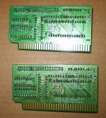
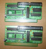
Here are what the two boards I built look like. I had a huge problem putting in the two surface mount resistors next to the LED Connector. I don't think I'm going to try doing the rest of the SMT parts. I may remove those two resistors. I have to check to make sure they aren't shorted.

I don't know why that part had to be SMT. there seems to be plenty of room for a non-smt part to have been used.

PA100004.jpg

PA100005.jpg
 
One thing I'm regretting is not using a right angle 40 pin connector, as it occurs to me that plugging in the CF card adapter is going to block some slots. I'm either going to have to replace the connector on one of these, or make some kind of cable.

Edit: I ended up buying three of these, as I have 3 CF adapters: http://www.ebay.com/itm/360668170207
 
Last edited:
Andrew,
I uploaded the spreadsheet to http://www.megley.com/temp/xtideparts.xls I highlighted in yellow the part number and price of where to buy each line item. The upper section is the Lo-Tech parts build (not bothering with the slot 8/LED SMD parts on the back), the lower is the XT-IDE Rev2. Any input is appreciated...

Wesley, I grabbed the Excel file, but it appears to me that both the top and bottom sections of the spreadsheet contain the same data. Maybe put it on different sheets instead?

tnx!

g.
 
One question...does the Lo-Tech XT CF card support two drives? I've got a dual slot CF adapter connected, but it will only recognize one of the cards.

Hi, great to see some of these coming together :) This is an interesting question - there's no reason that the adapter shouldn't support master&slave operation, but the BIOS has been configured not to search for a slave device when in XT-CF mode. The reasoning was that with the XT-CF(/v2/v3), there is only one header present and hence there could never be a slave device on those.

As for the SMT parts; there is very little space on the board hence I decided to just go with SMT for all the 'optional' parts. To solder them, some flux will be needed - I used EDSYN FL-22 syringe type. Then just tin the bit, place the component with tweezers and just touch the iron on the pad - solder will then flow onto the pad and stick the component.

Not sure about the coating issue - not had that problem. You can also just wash off the flux by running the board under a warm-to-hot tap.

Sorry for the delay in replying on all of this; workload has been a real problem recently. Glad you're getting these running though :)
 
BTW, there are some potential compatibility issues with the R565 BIOS caused by the late initialisation module. The BIOS should probably be built without that, for now.
 
This is an interesting question - there's no reason that the adapter shouldn't support master&slave operation, but the BIOS has been configured not to search for a slave device when in XT-CF mode. The reasoning was that with the XT-CF(/v2/v3), there is only one header present and hence there could never be a slave device on those.

Maybe we should remove that check, there's no point in having it if it's actually possible to use two drives. As an added bonus, it would also free up some ROM space. What do you think James?

BTW, there are some potential compatibility issues with the R565 BIOS caused by the late initialisation module. The BIOS should probably be built without that, for now.

How many machines actually need MODULE_VERY_LATE_INITIALIZATION? Seems to me it should be an option for the very few(?) machines that do but should not be included in the official builds (again, would save space). Alternatively, we could have an official build made especially for those machines.
 
Wesley, I grabbed the Excel file, but it appears to me that both the top and bottom sections of the spreadsheet contain the same data. Maybe put it on different sheets instead?

Sorry for the confusion...I used the Excel feature to split the same spreadsheet so I could see the header row at the top while scrolling the rest of the page...then split it vertically so I could see part #'s at the left while entering data at the right. It's all the same data, just broken up into four views. Make sense?

The top 13 rows (12 not counting the header line) are the Lo-Tech card, then there is a blank line (row 14), then the rest is the XT-IDE Rev2 card.

For the Lo-Tech card, probably cheapest to buy it all from Mouser (if you're in the US)...I only picked a few cheaper parts from Jameco since I was ordering other stuff for the rev2 card anyway. You'll notice I also opted to put the chips in sockets on the Lo-Tech card...if you trust yourself with soldering enough, you could probably leave those out as many have done.

Wesley
 
One thing I'm regretting is not using a right angle 40 pin connector, as it occurs to me that plugging in the CF card adapter is going to block some slots. I'm either going to have to replace the connector on one of these, or make some kind of cable.

Edit: I ended up buying three of these, as I have 3 CF adapters: http://www.ebay.com/itm/360668170207

I bought both types (straight and right-angle) and figured I would decide at build time. I went with the straight. In looking at it, I don't know that it would fit in a case with a right-angle connector and the CF adapter perched on top. I just did some looking at ISA card specs...looks like XT's allow for 4.2" height, AT's possibly 4.8". At a guess measurement, it would work in a case with 4.8" of height, but not 4.2". I'll probably just use one of the slot adapters so the CF card can be installed/removed from the back of the PC without opening it...assuming there are enough empty slots. Would be nice if there was enough room between the Lo-Tech card and the slot bracket to put the card and bracket in the same slot...I would have to look more closely...may not be do-able period based on the depth of the CF adapter and where the ISA slot begins.

What exactly does that ebay part do? Or is that what you soldered to the board? Looks like it's just a male to male converter...?

Wesley
 
Hi, great to see some of these coming together :) This is an interesting question - there's no reason that the adapter shouldn't support master&slave operation, but the BIOS has been configured not to search for a slave device when in XT-CF mode. The reasoning was that with the XT-CF(/v2/v3), there is only one header present and hence there could never be a slave device on those.

As for the SMT parts; there is very little space on the board hence I decided to just go with SMT for all the 'optional' parts. To solder them, some flux will be needed - I used EDSYN FL-22 syringe type. Then just tin the bit, place the component with tweezers and just touch the iron on the pad - solder will then flow onto the pad and stick the component.

Not sure about the coating issue - not had that problem. You can also just wash off the flux by running the board under a warm-to-hot tap.

Sorry for the delay in replying on all of this; workload has been a real problem recently. Glad you're getting these running though :)

Great to be having them come together. :) It's something of an ego boost to assemble something like that and have it actually work when you get done. :)

Can the BIOS simply be re-built to turn on the slave functionality? The CF adapter I've tried using first is one that has a CF slot on either side, so you have a master and a slave card on the same unit. I wasn't sure if I was doing something wrong or there was maybe something wrong with the adapter. They are definitely cheap! Soldering isn't all that pretty either! But hey, the price is right, and they seem to work fine. If there are enough empty slots, one can also use a pair of the CF slot type adapters and have both cards sticking out the back for easy swapping.

I went the easy route and skipped the surface-mount stuff. Figured it wouldn't likely end up in an XT slot 8, nor was the LED a big deal to me... Thanks for the tips though...always good to learn more about surface-mount soldering.

No need to be sorry...I imagine I can speak for everyone when I say I appreciate all the work you put into designing this cool stuff...not to mention the work selling the resulting boards. Just awesome! If you get more in down the road, I may have to pick up a few more...and have all my old machines with CF hard drives. :)

Thanks,

Wesley
 
The WIKI isn't clear. Which optional parts are needed for the LED and which for slot 8 compatibility? And, which slot is slot 8?

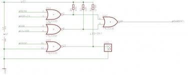
Thanks for the feedback - I've added an image with slot-8 marked (here). The optional components (see BoM) are actually all needed for both slot-8 and the LED drive. This is because there is insufficient drive available from a CompactFlash card (some, as little as 2mA or so) for general purpose LEDs, so one of the gates in U1 is used basically as an amplifier. Others provide the slot-8 card-select line drive. For anyone interested:

lo-tech-U1-logic.jpg

Maybe we should remove that check, there's no point in having it if it's actually possible to use two drives

Agree with this in principle - it just makes a potential delay in booting since some of the XT-CF lack a PD resistor on the status line. Delays aren't too much of a concern with 1980s PCs though :)


How many machines actually need MODULE_VERY_LATE_INITIALIZATION? Seems to me it should be an option for the very few(?)...

Again, agree.

Would be nice if there was enough room between the Lo-Tech card and the slot bracket to put the card and bracket in the same slot...I would have to look more closely...may not be do-able period based on the depth of the CF adapter and where the ISA slot begins.

This might work OK as the slot-bracket adapters (that I have seen) follow the PCI way of doing things, with the card attached to the bracket on the opposite side to that used for ISA cards.

It's something of an ego boost to assemble something like that and have it actually work when you get done. :) Can the BIOS simply be re-built to turn on the slave functionality?

That for me is the best bit too :) And thanks for the kind words. Yes I think we can make some changes to the BIOS - Krille is very much more in touch with that side of things mind.
 
About the slave drive and the BIOS...that would be wonderful! If it is as simple as re-building it per the directions, I can probably manage it...though if someone has all the tools already set up, etc, that would probably be much easier for them to do than for me to attempt it...

As for the slot adapter, I hadn't considered that they might be facing the opposite direction. I'll have to give it a shot and see if it will fit together in the same slot.

Al - that makes sense adapter-wise. The other thing to consider is that you can get IDE to CF adapters that are a board with a male connector, rather than the female ones that plug in directly.

Wesley
 
Back
Top