• Please review our updated Terms and Rules here

help for fix an 8096-sk

emilen72

Member
Joined
Mar 26, 2013
Messages
15
Location
Terni, Italy
Regards to all,
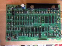
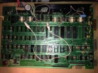
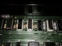
I recovered a pet that was in an attic for 30 years ... the board had much rust and dirt and some chips too...

This 8096-sk have a separate board that is plugged with a flat cable on the cpu socket... for now I have disconnected this and put the 6502 on the socket...
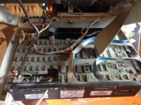
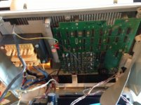
foto 1.jpg

foto 2.jpg

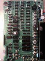
foto 3.jpg (board after clean and socket-in operation)

after a thorough cleaning, I tested the voltages and all are ok, tested with mutimeter and scope...

but at power on, no initial sound and the video stay black (monitor tube low voltage filament is red)...

Some months ago, I repaired a CBM 3032 that had ROM problems, now I thinking that the new 8096-sk had the same problems I unsoldered the rom, and I found one dead (901465-23) , I replaced as with an eprom but nothing to do ...same symptoms

then I tested the CPU and it's ok (put it in the 3032)... the reset circuit is ok (at the power on go low for a second then remains high)... the clock is ok ...

I unsoldered the two 6520 , the 6522 and the CRTC and put socket for these...

I put in a know working CRTC and no good news...

then I put the 6522 removed from 8096-sk in my CBM 3032 and seems ok, same uppercase characters ( without chip are in lower case ) ..

then I put the two 6520 removed for 8096-sk in the CBM 3032 and ... these do not work ... one makes a random sequence of characters that appear on the screen automatically as if it was typed from the keyboard ... the other one 6520 block the CBM3032 at the pre-boot screen, the entire screen full of random characters as when it have faulty rom...

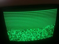
I also tried the monitor ... I connected the cable of the monitor of the 8096-sk to the motherboard of 3032 ... and the video work, even if the picture is not as I thought ...
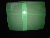
foto-1.JPG (3032 video signal on 8096-sk monitor)


Now some the questions before I start to investigate further:

1 ) it is normal that the video signal of 3032 is displayed so strange on the 8096-sk's 80 columns monitor?, or the monitor is to be repaired anyway?
2 ) the 8096-sk can operate without 6520 and 6522 on board? ok no boot sound but it work?

thanks to all and sorry for my bad english...
 
Last edited:
1 ) it is normal that the video signal of 3032 is displayed so strange on the 8096-sk's 80 columns monitor?, or the monitor is to be repaired anyway?

That sounds strange to me; as far as I know the 8096 is formerly an 8032 plus an expansion board (but don't trust me 100%, I'm not sure about this fact).

2 ) the 8096-sk can operate without 6520 and 6522 on board? ok no boot sound but it work?

If I remember fine, all the PET series (including PET 2001/8, 3032 and 8032) boot fine without the two 6520, they go until the boot screen phase and then hang (no cursor).
But you need the 6522...

Now, about the boot problems, if ROMs are ok, it could be a RAM problem. Have you an eprom programmer? If the answer is yes, go there: http://www.verrua.org/pet_repair/index.html, scroll until to find the pettester rom link (in the second half of the page), get the 8032 image and follow the instructions about how to build an adapter and what to expect from the pettester. It will help you at least to decide if it's a ram problem or not.

My experience: fixing PETs, I have had more troubles from bad socket (that makes bad and/or intermittent contact) than from bad ICs! So keep in mind that sockets are problematic too!!!

And, of course, I'm sure that Dave, Mike and the other gurus here can (and will) help you in a better way!

--Giovi
 
Last edited:
1 ) it is normal that the video signal of 3032 is displayed so strange on the 8096-sk's 80 columns monitor?, or the monitor is to be repaired anyway?

I think that the monitor is OK. It expects a horizontal rate of 20KHz and your are sending it a rate of 15KHz from the 3032.
 
1 ) it is normal that the video signal of 3032 is displayed so strange on the 8096-sk's 80 columns monitor?, or the monitor is to be repaired anyway?
The 'video-on' signal looks inverted between the boards, hence the black on white picture and the fact you can see the horizontal retrace path.
 
@ dave_m

so can't use a composite video adapter, as for 3032, during the fix attempt time for no stress the original 8096-sx monitor :-(
 
little step haead
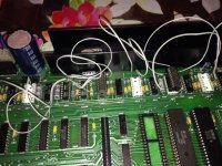
I have desolderd the lower ram bank and put 8 socket in place, then I have put two 4464 in two sockets with a little adapter and linked D1-D2-D3 data pin to the relative pin of the six free sockets
image.jpg

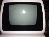
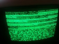
with the 6502 and the 6545 and no PIA and no VIA installed, on power on monitor show this
image.jpg

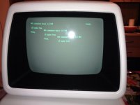
with PIA keyboard related this:
image.jpg

any suggest why it show three time the same message?

any suggest to looking for?

thanks
 
hi, some step ahead, again...

I have thought that the error above was due ram addressing trouble, or buffers ls244 related... I have tested all link CPU, Buffers and ram and is all ok...

Desoldered the three LS244 UE8-UE9-UE10 and putted socket... retested the link, all ok... but when I have re-inserted the original LS244... no more video... the crisp sound is present but no video...

I have tried some other LS244 (new) and nothing to do!!!

After taht I have burn and eprom with pettester.bin for 8032 founded on this site http://www.verrua.org/pet_repair/petester_8032.zip but originally made here (anybody have a new version?)...

putted in the kernal socket... and no luck... same black screen

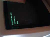
But for looking for a bit of luck I want to test some other LS244 but... in my warehouse I have only two HC244... not the same than the original chip used by commodore... but I have tried these on UE8-UE9 and bingo... the pettester work...BUT WHY????

141b6fbc53b091057d436b6b7a978a9f.jpg
70d8d781b9f6589fd645297fa02fd92c.jpg

I have left an ls244 (NEW) in UE10 but I have discovered that with or without this chip inserted, the pettester works????

any idea where looking for?
 
But for looking for a bit of luck I want to test some other LS244 but... in my warehouse I have only two HC244... not the same than the original chip used by commodore... but I have tried these on UE8-UE9 and bingo... the pettester work...BUT WHY????


I have left an ls244 (NEW) in UE10 but I have discovered that with or without this chip inserted, the pettester works????

any idea where looking for?

OK, first of all, the PET 8032 version of Pettester is only a slight modification of the PET 2001 version which will initialize the 6545 CRT Controller. So it only tests the first 1K of video memory (12 lines by 80 characters) rather than the entire 2K video needed for the 8032 (25 lines by 80 characters). That's why the bottom of the screen still has garbage characters.

As to why the HC244 works better than the LS244, I do not know. Both should work although the HC has a better voltage swing and more drive capability.

If UE10 is missing, you can not address more than 128 bytes of memory. You are simply using the same area of RAM memory (128 bytes) from address $3F80 to $3FFF no matter what address PETTESTER is trying to test. That is why the PET will not boot as it needs good memory from $0000 to $0400 to boot. Make sure you have a good chip in UE10 and see if you can boot. you are getting very close. Good work!
 
thanks dave_m for the reply...

I have put a third HC244 in UE10 but no boot with original rom... pettester boot, and show the same images above.... but how can determine if they addressing all 1K of memory and not only 128bytes?


so any chance to get a more recent pettester? I read about some 2K modded .bin with different memory path test and address check... but no .bin is available for download :-(


I have a scope but not sure what test to do....
 
I have a scope but not sure what test to do....

With a scope you have a lot of options. Of the things that can prevent a boot, bad low RAM or a bad ROM are two of the common ones. Let's try to check the address path to make sure that RAM is being properly addressed.

You will have to make a NOP Generator out of a 40 pin socket. The socket will be placed under the 6502 CPU chip. It will force the CPU to generate endless NOP instructions. The purpose of this is to cause the Program Counter (PC) to increment continuously over all address space (64K). There will cause square waves on all address lines. This will be easy to check on the scope. If you come to an address signal without square waves, you have found a problem of a bad chip or a bad connection.

Search this forum for messages by MikeS with the term "NOP" or "NOP Generator" and see if you find the instructions on modifying a 40 pin socket. So as not to damage your CPU chip, I would also invest in a 40 pin chip puller and a 40 pin insertion tool.

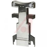
40 pin Extraction Tool
Extract.jpg

40 pin Insertion Tool

40pin_tool.jpg
 
Thanks for the tips... and do you think that the NOP generator can be build over the kernal eprom socket too? It have all the needed signal...
 
Thanks for the tips... and do you think that the NOP generator can be build over the kernal eprom socket too? It have all the needed signal...
More complicated, only works if the problem is not in any of the data lines, and conflicts with other RAM & ROM chips; also, in later model PETs the kernel ROM is not socketed whereas the CPU generally still is.

But yes, if you want to go that route for some reason here it is:

http://www.6502.org/mini-projects/nop-gen/nop-gen.htm
 
Last edited:
Thanks for the tips... and do you think that the NOP generator can be build over the kernal eprom socket too? It have all the needed signal...

No, you do not want to put the NOP pattern ($EA) on the actual data bus. You want them only at the isolated CPU pins or else you will short ROM and RAM outputs.
 
More complicated, only works if the problem is not in any of the data lines, and conflicts with other RAM & ROM chips; also, in later model PETs the kernel ROM is not socketed whereas the CPU generally still is.

But yes, if you want to go that route for some reason here it is:

http://www.6502.org/mini-projects/nop-gen/nop-gen.htm

Mike,
That circuit will only work correctly on boards where all RAM and ROM have been removed otherwise when those devices are chip enabled, they will alter the NOP pattern as you mentioned and then no more square waves.

Your own NOP Generator instructions were the clearest. I wish the search function were better to find such old messages.
 
Mike,
That circuit will only work correctly on boards where all RAM and ROM have been removed otherwise when those devices are chip enabled, they will alter the NOP pattern as you mentioned and then no more square waves.
Yeah, sorry; my peculiar brand of irony often gets lost and muddies the waters...

I did say that it "conflicts with other RAM and ROM chips" and the article in the link also mentions that it is for new 6502 projects and should be used with only the CPU and NOP generator in the circuit; I don't know why the OP would rather use a ROM socket instead of the suggested simpler CPU "sandwich," but if he doesn't mind removing all the other RAM, ROM and I/O chips on the bus, has a free socket, is certain that the data lines are OK etc., then sure, a published circuit exists.

In all fairness though, I see that the Davison EPROM version does Google before the CPU version, which could be misleading unless you read the fine print; thanks for emphasizing that it is NOT appropriate for a PET.
 
Last edited:
fixed :)

foto-2.JPG


with the NOP I have discovered that the pin 14 of the UE10 have a break in the paddle... and that the triple screen was a micro-short on two pin of video memory...
all buffer LS244 is ok and during the test even with HC244 (UE8-UE9-UE10 and UD14) the machine work great...

in the end this 8096-sk have this trouble:

1x basic rom dead
2x PIA6520 dead
9 x ram 4116 dead
1 x paddle breack by rust
1 x micro short on one pin of video memory


During the test I have used two 4464
foto 1-1.jpg

but as definitive I have put nine 4164 instead 4116...

foto 3-1.jpg


foto 2-1.jpg

now I have to test the 64k expansion board... this when connected don't change the boot memory amount and a special program is needed...

thanks to all for the help :)
 
Back
Top