• Please review our updated Terms and Rules here

Help identify the value of these components please!

ChrisCwmbran

Experienced Member
Joined
Oct 11, 2011
Messages
483
Location
Cwmbran, Wales, United Kingdom
Hi all.

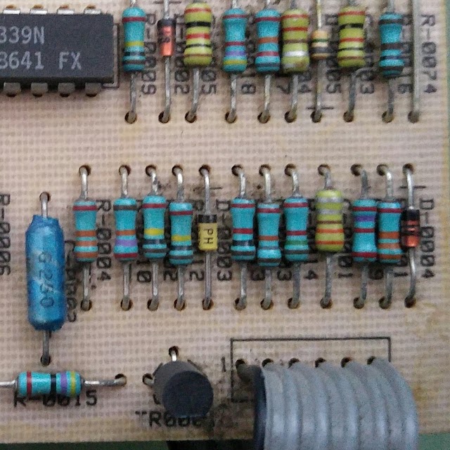
In this image there are three components ringed in red. I sent this picture to one of the UK's largest electronics component suppliers and even they don't seem to be able to put values on the three components.

WP_20160129_15_35_45_Pro.jpg

Can I have some answers or at least opinions please?

Thanks in advance!
 
This question is very confusing. Are you asking what those components are? They are resistors. Are you asking if they are rare or worth a bit of money? They aren't.

You probably didn't get an answer from the recycler because they may have thought you were trolling.
 
Low value resistors. The top one is 3.31 ohms 10%. See:

resistor-color-chart.jpg
 
This question is very confusing. Are you asking what those components are? They are resistors. Are you asking if they are rare or worth a bit of money? They aren't.

You probably didn't get an answer from the recycler because they may have thought you were trolling.

I didn't mention a recycler. I communicated with a major UK supplier of new electronic components about what current equivalent part numbers are.

They were unable to help with two out of the three items. So far I have differing answers from all corners. Finding two people who agree seems impossible.
 
Try filling out the form http://www.digikey.com/en/resources...version-calculator-resistor-color-code-6-band Switch to the 4 and 5 band selector to read the values for the other ones. I could punch the values myself but the end result would be the same.

Do you happen to have any form of documentation for the underlying board? That should provide a reasonableness check for whatever values you get.

Its one of the three boards from inside the PSU of an IBM 5170. I've spent ages looking for schematics with no luck.
 
I should apologize -- I believe I completely misunderstood the tone of your post. Most people who post terse, short messages like that are asking for the monetary value of their collectibles... what I should have realized is that you were asking for the resistor values of the highlighted resistors in your picture. Sorry about that!
 
I agree with bobba84, they look like 2% resistors to me. I can see the confusion though, they're fairly unusual parts, not rare, but noteworthy these days. You may have just got an inexperienced member of staff but they're almost certainly resistors, there's a slim chance they're inductors, but a quick check with a multimeter should clarify.
 
It looks like the other parts have designations under them. I see "D-0004" under the diode, and it looks like other resistors on the board have codes that start with "R-xxxx" -- almost certainly resistors, the ceramic substrate body is wrong for an inductor or capacitor.
 
Well I can quantify things a little more. A defective chopping transistor had a negative effect on this area of the PSU:

WP_20160201_20_59_10_Pro_LI.jpg

The one resistor is totally blown so having cut it out of circuit it reveals some information:

WP_20160204_10_15_23_Pro.jpg

As Glitch pointed out the designations are marked on the board but they seem to show that the "green resistor" is in fact a capacitor.

Whilst I understand the colour coding of resistors I don't understand a) how you know which way to read them i.e. from what end. Surely the resistors could be soldered either way round? And b) WHere some appear to have a gap where there would be a band are they 4 colour codes or are they 5 colour codes where one digit isn't expressed?

I'm just looking to order three items to replace these three parts and am very confused what parts to order!
 
I also have a faulty AT PSU like yours, but mine is burnt in another point

VRsw2ps8dROZ2WQbpEyqdCIGOpH25B63spzPfGTOkjpMYE0A6dCDkHrqPFml0iH8XT4VE_g85uJBBwo9YN6oL9LdnKRWB1QabxY1T6w7cQJ2Gbj5kEbw2tPa22EQPQso9VOa13m-V6uWhSmIkWWbZt640Rf_uK0EVD5yQGKCmGHHOG6IFDyRGx7_v55gUymhbw5TCQItR_2w7oEC8npW3hyS09yyDud-LyXYPU56PeHIMrrm1CEJQ9XJ9QLbdDiwZvaonPviXx0N7I6ZerBrEv_5Msi6VPMtpLIN5J0lITt7knWGpeIkcihFpNXrJboYd9al7graQNOrhztFSokcDDHz9nQ-__lG9bJkjNd26nyrE8m7-F4wQHKphlOL6lYlB2VE-4ztedoNJ087n6Do5zLuhP_FqrxrI9fYw5cKcI1QIXHEmtfCzSlrqAPejqU11H9mHHPb95YoYJ7_3YZ-D1oP6-rT6ECfwcxQ8QUbKaQnbb7fC-xCSjQzA0WI-u0rnyPYzXgxOoDZF904l8B7s6SKi5C5dFBOywXqNu0-RNPZpHRlPbTTwVactZuP853ZRTZf=w640


I will try to measure those values.
 
.....Whilst I understand the colour coding of resistors I don't understand a) how you know which way to read them i.e. from what end. Surely the resistors could be soldered either way round? And b) WHere some appear to have a gap where there would be a band are they 4 colour codes or are they 5 colour codes where one digit isn't expressed?

Some resistors you'll see the first band is wider than the rest, Also see the FAQ on this page for more, There is also Free Resistor color code calculators around the net, Example here.
 
Just so you know, I can tell you for a fact that some of those resistor look alike are actually capacitors (they can be substituted by ceramic caps). Look for the board written marking under each component for example, if it starts with a D- then its more likely a Diode. A Letter R- (a Resistor), a C- (a capacitor), Q- (transistor), etc...
 
If you're looking for a show of hands then, starting with the near one next to the diode:

brown / brown / brown with a red tolerance band: 110R, 2% tolerance

Next one, which happens to be fitted the other way around

red /violet / red with a red tolerance band: 2.7K, 2% tolerance

The next one is potentially more tricky. If it is a resistor it is a four band resistor in which the first three bands convey the value digits and the fourth band is the multiplier.

orange / orange / brown / silver is 3 3 1 times 0.01R, or 3.31R

However, looking at your later pictures all the pale green components whose component numbers can be seen are capacitors.
 
Last edited:
Because of the confusion about banding and the difficulty discerning colors from your photo I would recommend not drawing any inference from the banding, but actually de-solder one leg and check with a meter.

For example, the top "resistor" could be a five-band code with orange, orange, brown, grey, silver (reading left to right). If this were the case you would be looking at mega-ohms of resistance.

Don't guess, measure would be my advice.

-CH-
 
Back
Top