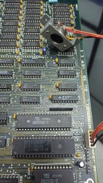
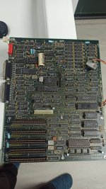
I have a bondwell BW38 motherboard that always shows a "KEYBOARD ERROR. PRESS F1" message in bios, no matter if the keyboard is plugged or not. I can see a 74LS322 next to the 8255 so I assume it uses an XT keyboard. How can I find where is the damaged component?
- VCF South West - June 14 - 16, Davidson-Gundy Alumni Center at University of Texas at Dallas
- VCF West - Aug 2 - 3, Computer History Museum, Mountain View, CA
- VCF Midwest - Sept 7 - 8 2024, Schaumburg, IL
- VCF SoCal - Mid February 2025, Location TBD, Southern CA
- VCF East - April 2025, Infoage Museum, Wall NJ
-
Please review our updated Terms and Rules here
- Forums
- Companies
- IBM Computers, PCs, Clones and Descendants
- PCs and Clones (XT and early AT class machines)
You are using an out of date browser. It may not display this or other websites correctly.
You should upgrade or use an alternative browser.
You should upgrade or use an alternative browser.
How can I diagnose the keyboard port of a XT Clone board?
- Thread starter nestor
- Start date
Stone
10k Member
Have you tried another keyboard? Have you wiggled the keyboard connector? Have you used this keyboard in another machine? Have you tried an AT keyboard? If you have answered yes to all these questions, you're screwed. ") Or at least the board is.
Or at least the board is.
Or at least the board is.Chuck(G)
25k Member
Very very often, the 5-pin DIN connector on the board comes loose compromising the soldered connections or worse, a trace is broken or lifted.
But basically, all of the XT motherboards use nearly identical keyboard circuits.
But basically, all of the XT motherboards use nearly identical keyboard circuits.
Have you tried another keyboard? Have you wiggled the keyboard connector? Have you used this keyboard in another machine? Have you tried an AT keyboard? If you have answered yes to all these questions, you're screwed.
Yes, the board is screwed
I tried with a keyboard and with the AT2XTKBD adapter that I use with other XT machines, but nothing, the board doesn't receive key presses. I installed the generic XT bios from Plasma and managed to boot from a floppy disk, launching in autoexec.bat Prince of Persia in demo mode for 30 minutes, so the board seems to be working.This board doesn't have a DIN5 conector, only a 5 pin header. GND and VCC are easy to discover, DATA is tied to 74LS322, CLOCK comes from a 74LS125 and /RESET is the last one.
Any idea before unsolder ICs one by one?
The first thing I would suggest is that you get your multimeter out and check to ensure that the keyboard socket is providing a +5VDC supply to the keyboard (if you can make a pass-through adapter see if it's still 5VDC with the keyboard plugged in).
If the keyboard has power, I'd suggest then getting a logic probe (or oscilloscope) and check the keyboard clock and data signals to see if the bios boot diagnostics are working. When the XT boots it sends a command to the keyboard, and if it does not get the correct response it puts up the 'F1 Error' message.
You should see a series of short pulses on the clock and data lines, and they should be 'nice' 5VDC TTL signals.
Looking at the schematics for the IBM XT Keyboard (Sheet 9 of 10) there are some capacitors on the lines for signal conditioning. It's a good bet that one or more may have failed and shorted out.
You could also just try pulling the 'LS322 in case it has failed.
Have fun
Sean
Floppies_only
Veteran Member
The first thing I would suggest is that you get your multimeter out and check to ensure that the keyboard socket is providing a +5VDC supply to the keyboard (if you can make a pass-through adapter see if it's still 5VDC with the keyboard plugged in).
Sean
Sean et. al. Multimeters put up with a lot of abuse but I was taught that the way to measure voltage was to put the red positive lead on the positive supply of voltage and the black negative lead on the ground or negative voltage line. A voltmeter is a high-resistance circuit that shunts a little bit of current away from the device under test. To measure current, you have to have all the current go through the meter, unless it is an AC clamp on style meter that measures the magnetic field surrounding the conductor.
I might be a good idea to tap the ends of the test leads onto a grounded piece of metal before touching the circuit under test, to dissipate any static charge it might have picked up.
Sean (also)
Thanks floppies_only - but I've over 35 years experience with electronics so I think I can stumble my way through just fine
BTW - for the purposes of this thread, the resistance of the multimeter is insignificant. Your 'bargain basement' multimeter will typically have a resistance of 1 meg - resulting in a parasitic draw of 5 micro-amps assuming a 5VDC supply. A better meter will have a higher resistance. For the purposes of testing a keyboard to see if there is power being delivered (i.e. testing for a broken socket) or if there is a short circuit, or if the voltage is significantly different from the 5VDC (i.e. below the LS322 Vmin of 4.5 or above Vmax of 5.5) such an infinitesimal load won't affect any decision (and probably is beyond the precision of the meter).
BTW - for the purposes of this thread, the resistance of the multimeter is insignificant. Your 'bargain basement' multimeter will typically have a resistance of 1 meg - resulting in a parasitic draw of 5 micro-amps assuming a 5VDC supply. A better meter will have a higher resistance. For the purposes of testing a keyboard to see if there is power being delivered (i.e. testing for a broken socket) or if there is a short circuit, or if the voltage is significantly different from the 5VDC (i.e. below the LS322 Vmin of 4.5 or above Vmax of 5.5) such an infinitesimal load won't affect any decision (and probably is beyond the precision of the meter).
Last edited:
jmellidg
Experienced Member
Excuse me for post to this thread 10 years later... But I have the same problem, same computer.. Have you fixed the issue??? Thanks!!!
Hi jmellidg,Excuse me for post to this thread 10 years later... But I have the same problem, same computer.. Have you fixed the issue??? Thanks!!!
If everything else fails, including all described (please measure traces continuity), I would:
1- Look at the keyboard controller chip: test it with the oscilloscope and specs/pinout. If it does not work, swap it with another compatible controller and test again.
2- Find another version of the ROM for your board and test it. Many different ROMS in minuszerodegrees and similar sites. Some boards support some "generic" BIOS from other manufacturers.
3- Find a board diagram and test the connections and data beyond the controller back to other ICs, to identify if there's something talking to the keyboard controller
I wish you the best of luck !!
jmellidg
Experienced Member
Thank you very much, I'll do
modem7
10k Member
So, a Bondwell BW38 that always displays "KEYBOARD ERROR. PRESS F1".Excuse me for post to this thread 10 years later... But I have the same problem, same computer.
It could be either the keyboard, or the keyboard interface circuitry on the computer's motherboard. Did you try another (known compatible) keyboard?
The Bondwell BW38 is an XT-class computer. The OP wrote, "see a 74LS322 next to the 8255", which informs me that the motherboard is most probably using a variation of the 'standard' keyboard interface circuitry found in most PC-class and XT-class computers. So there will not be a keyboard controller chip on the motherboard. As an example, the keyboard interface circuitry used on the IBM XT motherboard is shown at [here]. PC-class and XT-class computers use variations of that. For example, the Compaq Portable supplies +12V to the keyboard, not the norm, which is +5V.
If we assume that the Bondwell BW38 is doing the standard PC/XT thing:
The computer's power-on self test (POST) pulses the keyboard CLOCK line. The keyboard sees that as a request to do a self-test. The (good) keyboard then sends the byte of AAh to the motherboard. An example technical diagram is at [here]. Presumably, the POST is displaying "KEYBOARD ERROR. PRESS F1" because the POST is not seeing AAh. That could be due to the keyboard or faulty keyboard interface circuitry on the motherboard.
jmellidg
Experienced Member
Hi, thank you very much for your answer. I've tested with several keyboards and test the bondwell keyboard in other xt's, the keyboard it's OK.
When I bought this computer, worked fine, but sometimes I had problems with the "keyboard". Normally if I detach it and plug it again, it worked, but sometimes didn't work. I thought that it could be bad solder in the connector.
Disassembly the unit and changed a bunch of capacitors, the battery and reflow the keyboard connector solders. I changed too the rifa capacitors of the power supply.
Put all things together and started the computer, and fine! Everything works.
Then I try to put all the things together in the case and it never start again. No way, always keyboard error.
I'm not an expert with electronics so I don't really know what to do next..
I was doing track check and test the capacitors again.
I checked measures with other xt motherboard that uses the same 322 and there was different continuity with pins in the 322 and the data pin of the connector. I'm a little bit lost at this moment... Jaja
Thank you for your help
jmellidg
Experienced Member
modem7
10k Member
I remember many years ago, someone on these forums had a motherboard that worked out of the case, but not when fitted in the case. It turned out that when the motherboard was screwed into the case, part of the motherboard's circuitry was somehow being shorted out to the (metal) case.Then I try to put all the things together in the case and it never start again. No way, always keyboard error.
Does the symptom only appear when the motherboard is in the case ?
Did the connector get plugged in the wrong orientation ?

I wrote earlier, "PC-class and XT-class computers use variations of that."I checked measures with other xt motherboard that uses the same 322 and there was different continuity with pins in the 322 and the data pin of the connector.
Expecting different models of motherboard to use exactly the same keyboard interface circuitry (and that is more than simply the type of chips used) is invalid.
So, there's the question about whether the symptom only appears when the motherboard is in the case.I'm a little bit lost at this moment...
Beyond that, it is then a case of using suitable test equipment to look at various places in the keyboard interface circuitry. I have helped people do that diagnosis. In some cases, I had to create small amounts of diagnostic code for the owner to put into a ROM (replacing the existing BIOS ROM).
You do not have a circuit diagram for the motherboard, but initially, one will not be required. For example, a logic probe is expected to show the POST pulsing the CLOCK line. For example, on the LS322 shift register, a logic probe is expected to show a pulse on pin 12 each time that a key is pressed. Beyond certain basics like that, you would need to work out for me what the circuit is (components, interconnections, etc.)
Last edited:
jmellidg
Experienced Member
Hi, you are so kind!! I'm sure that at this moment, no work at all, in or outside the case.. But now I'm doing the tests just with the power supply, graphic card and the keyboard. About the way to plug the connector, there was the original orientation when I open the case, and is in the same way that the near connectors (reset and power supply stuff). Additionally I test continuity for the 5v and ground pins of the keyboard connector.
I have a little oscilloscope DS203, and I'll try to test the pulse as you say. I tested that there's 5 volts in the keyboard +V pin and the lights in the keyboard works ok.
I have a little oscilloscope DS203, and I'll try to test the pulse as you say. I tested that there's 5 volts in the keyboard +V pin and the lights in the keyboard works ok.
modem7
10k Member
Normally (repeat: normally), lights on the keyboard indicate an AT-class keyboard (and yes, some support XT as well).... and the lights in the keyboard works ok.
A photo of the Bondwell BW38 that I see online shows no lights on the keyboard.
Are you sure that the keyboard you are using supports the XT keyboard protocol?
jmellidg
Experienced Member
Yes, it's the same computer but it has lights in some keys, I'll attach you a photo tomorrow, by the way I'm from Spain, its 22:30 here.. Jejeje
I test the continuity of all keyboard connector pins to the motherboard, and are all fine, thanks!!
I test the continuity of all keyboard connector pins to the motherboard, and are all fine, thanks!!
modem7
10k Member
That's okay. I don't expect instant replies. This is a hobby.
(Well, unless someone here needs a vintage computer fixed quickly because it is controlling a vintage online nuclear power station )
(Well, unless someone here needs a vintage computer fixed quickly because it is controlling a vintage online nuclear power station
)jmellidg
Experienced Member

Hi again,
Very good advice from modem7 indeed. I should add that it would be useful to install the board into the case without plugging the power and peek for continuity with the multimeter between all power connectors and the case (basically +5, +12, -5). If you get continuity apart from the negative pole, voila !!!.
Que bueno que estés en Madrid. No me había fijado antes ;-)