billdeg
Technician
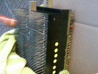
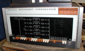
Here are some card slot pics from the MARCH pdp 8. At least you'd know the card order for this machine. It's from the R.E.S.I.S.T.O.R.S club of the 60's. Claud Kagan is in some of the photos, who donated the machine to our club in 2008. These are pics of the day he donated the pdp8 to us. As you can see, the computer artifacts were stored in his barn. You may have heard stories - a few years later the barn burned down taking a Burroughs 205 with it.
http://vintagecomputer.net/tcf_2008
http://vintagecomputer.net/tcf_2008