The topic has been brought up a couple times so I did an experiment with what I remembered from doing this testing years ago on flybacks. The biggest requirement is an oscilloscope that has a horizontal gate output usually on the back
of the scope. For this test, I used an Apple //gs color display model A2M6014. Reference this schematic: http://apple2.info/download/IIgsMon2b.pdf
With the CRT display totally disconnected from power and computer, put the scope across the primary side of the flyback between the B+ and collector of HOT (pins 1 and 2) polarity doesn't matter. Use a x10 probe for least capacitive load.
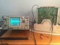
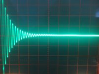
Put a lead from the scope gated output through a .001uF capacitor to the positive of the scope probe. Set horizontal to .1ms/div and vertical 10mV/div. Here is the setup and resulting good waveform:


A good ring is a parabolic shaped decay of 8-10 rings. I don't remember the magic number, exactly. If you purchase a tester, it is usually a ring counter and the manual will give the # of rings acceptable.
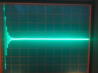
As a test I jumpered pins together to simulate shorted turns. I tried 2-5, 3-4, 6-9, 9-10. All gave the same low ring, non-parabolic wave form of this:

Notice the very rapid almost straight line decay within 4 or 5 rings. A ring tester would definitely give a low count, too.
I experimented shorting the secondary capacitors C512,C514,C515 but they had absolutely no effect on the good ring waveform. I also shorted the 2nd anode lead to ground and again, no effect.
However, when I short the diodes D506, D507, or D508 it does pinch the waveform just like a shorted turn !!!
So, if a ring test fails, secondary diodes should be checked / lifted also... interesting, I may have failed some good flybacks in my past
Fun stuff !!
Larry G
of the scope. For this test, I used an Apple //gs color display model A2M6014. Reference this schematic: http://apple2.info/download/IIgsMon2b.pdf
With the CRT display totally disconnected from power and computer, put the scope across the primary side of the flyback between the B+ and collector of HOT (pins 1 and 2) polarity doesn't matter. Use a x10 probe for least capacitive load.
Put a lead from the scope gated output through a .001uF capacitor to the positive of the scope probe. Set horizontal to .1ms/div and vertical 10mV/div. Here is the setup and resulting good waveform:


A good ring is a parabolic shaped decay of 8-10 rings. I don't remember the magic number, exactly. If you purchase a tester, it is usually a ring counter and the manual will give the # of rings acceptable.
As a test I jumpered pins together to simulate shorted turns. I tried 2-5, 3-4, 6-9, 9-10. All gave the same low ring, non-parabolic wave form of this:

Notice the very rapid almost straight line decay within 4 or 5 rings. A ring tester would definitely give a low count, too.
I experimented shorting the secondary capacitors C512,C514,C515 but they had absolutely no effect on the good ring waveform. I also shorted the 2nd anode lead to ground and again, no effect.
However, when I short the diodes D506, D507, or D508 it does pinch the waveform just like a shorted turn !!!
So, if a ring test fails, secondary diodes should be checked / lifted also... interesting, I may have failed some good flybacks in my past
Fun stuff !!
Larry G
