• Please review our updated Terms and Rules here

HP 9845B Workstation and a lot of Extras

That took for goddamn ever!
...and they didn't work.

So plan B was that because the good board and my bad board were electrically he same but different revisions I stripped out the two IC's, four resistors, one filter cap and a jumper that made mine different form the other. The result is all the previously suspicious signals cleaned up immediately. Unfortunately that didn't fix it either! >:/
Another thing I noticed is I oopsed when previously testing the optocoupler and installed it backwards. I swapped them between boards so my board had a known good one and the other had the questionable one which upon testing worked so no, I didn't blow the optocoupler. The 555 was also replaced for sanity sake.

Due to the fact there's so few IC's I'll proceed with swapping chips between boards to see what happens.

Edited: Every IC and transistor on that side of the board has now been swapped between eachother and the problem did not move. Dammit.
 
Last edited:
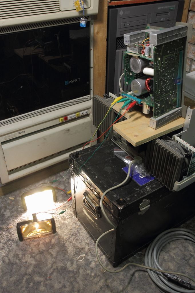
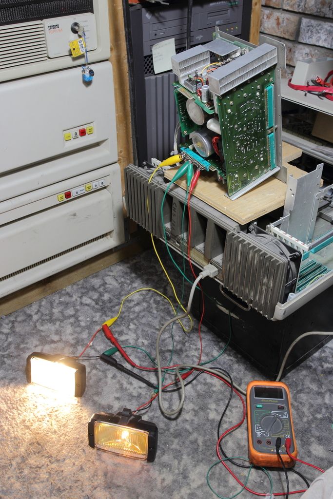
I had a few loose ends clean up earlier than expected so I was able to load test tonight. The loads were to vehicle fog lamps. At 5v they have a 4A inrush load and a 1.5A nominal draw and at 12v they have a 3A inrush load with a 2.5A nominal draw. That should be enough.
 
I got it. OMG YES! After a goddamn year on and off of troubleshooting I've isolated the faulty component.

U1 and U2 on the Low Voltage board are a set of 1820-0477 IC's that the HP cross reference seems to call OP-Amp chips. I"m assuming they came in matched pairs so after transplanting just about everything between the boards I found that when the pair moved the fault moved with it. The IC's can be purchased locally (for me) from Sphere Research. The non-HP part umber is LM301.
 
Last edited:
Yes, but keep in mind that a heat gun is a good way to implode a CRT.
How so? There's a vacuum inside and hence pressure inside the tube will not change with temperature. Also, on the tube's neck, where the glas is very thin, is a heating element that gets very hot and will not make the CRT implode either.
 
It's the result of thermal expansion and contraction. The stress on the glass will cause it to crack at which point because of the vacuum even a microscopic failure will instantly lead to catastrophic failure of the envelope.

Anyways my power supply successfully completed final testing.

IMG_7131.jpg


Before I can proceed however we're STILL not done with power supplies. In throubleshooting my PSU with a donor unit I accidentally blew up the clean-output board on the donor. It must be repaired before it can be returned. It is a FAR more simple board than the Low Voltage board so the odds are either a diode or a transistor did not like me forcing the PSU to run by rapidly power cycling it.
 
Finally had a few hours of free time to sit down and look at the remaining power supply fault. Started with testing the main regulators and transistors on the board. This new desoldering tool is fantastic on these larger traces so I can pull them out and test them individually.

Q1 and Q3 tested okay. I moved to U1 which is a 7912CK -12v 1.5A TO-3 voltage regulator. It will begin regulating fine until it hits 1.4v on either the input or output, then collapses back to 0v. I added a 1K resistor across the output as a load. I get up to -1.53v but then collapsed again. I think we found the problem. The created -12v does go to the master output edge connector however loops back into the power supply via P3R-D to the Power Supply Mother Board's logic section, where I guess it detects the missing -12v and shuts the power supply down.

Now to find that regulator. It's an obsolete part.
 
aaaaaaaand I screwed up testing that regulator.
The replacement arrived and was dropped in but there was no change. I pulled it back out and tested again and it seems like I must of screwed up my cabling arrangement for testing on the bench as both the repalcement AND THE ORIGINAL worked fine. Negative voltage regulators are a pain in the ass to test. >:U

Okay, so lets stop and look where we are:

-We have two power supplies. One that is mine and one that is on loan.
-The on-loan unit works. All of its boards function and it generates in-spec voltages.
-My unit worked. It would also generate a stable output until board swapping and testing caused the Clean Output board to fail.
-What happens if I swap out my bad board and put the board from the known good supply into mine? My power supply now works.
What if my bad board goes in the on-loan unit? That power supply fails to operate.
-The fault I accidentally caused is isolated to my Clean Output board. We know this because of the above test where we confirmed the rest of the power supply was functioning once the faulty board was swapped.
-Why is the power supply shutting down with this faulty board installed? There is a voltage either nonexistant or immediately out of tolerance which feeds back to the safety circuit in the PSU and shuts it down
-Can the monitoring lines be tapped and watched when power is applied? No, because I do not own an oscilloscope capable of storage.

So the logical thing to do next while it is the unlikely problem is to recap the board. There are five capacitors, all of which are 40 years old. They were pulled and ESR tested and gave excellent readings but were replaced anyways.

CGS_7810.jpg

http://i11.photobucket.com/albums/a166/ballsandy/Computer related/CGS_7810.jpg

This was not the solution. The next step was to pull all of the diodes out of circuit (14 in all) and test them one at a time with a DMM that has a diode check setting. They all seemed to read normal (read high or infinite one way and low the other) I'm about 50% confident on CR1 which according to the schematic is a zener.
The -12v regulator was retested (with the test cabling properly sorted!) and given a half amp load with no problems found.
The 2N4441 SCR was retested with a simple breadboard circuit and found to still be good.
The three resistors on the board were tested and found to be good.
The lone 2N2222a was removed and tested in a transistor tester and seemed to be okay.
The three induction coils look physically okay
The transformer blowing a winding is unlikely as the windings look to be very heavy duty

The only thing I cannot say 100% on is the 2N633A high output transistor. I do not have a diagram for a simple test jig to verify it and replacements are too expensive to blindly replace it.

Edited: aaaand like that, I found another anomaly.

There is one winding on the transformer that does +5v. Both sides leave and go through a 1901-0792 rectifier diode. That I can tell they are identical.
CR14 is one side and CR15 is the other. When pulled completely out of the circuit CR14 reads 0.134 on the diode check. That seems okay.
CR15 however (the bolt-in rectifier diode with the orange wire and the red pen mark on the side) initially starts infinite and over a minute or two climbs down to 1.32, which is unusually high, so I suspect it is extremely leaky.
 
Last edited:
SUCCESS!

IMG_9745.jpg


CR15 was bad. Presumably I popped it during earlier testing. CR14 and CR15 had to be replaced as a pair but once swapped the +5 and +12 came up as they should. The rails were both a little low but that was likely because it wasn't a proper load.
You will however notice that one of the heatsinks have fallen off..... I have access to thermally conductive epoxy and will have to reattach that, then finally after two years we can reassemble the machine and ask "what do we want to do next?" Should I proceed with recapping the monitor or throw everything in and see if it passes the smoke test?
 
Nice going! Huge respect for the amount of work you've done bringing this thing back from the dead. Hope to see it in action soon. :)
 
After adding a little adapter so I could attach a load with the power supply installed in the mainframe I was able to verify that all the voltages at the test points were good and went ahead removing the loads and reinstalling all the boards.
I need to verify what screws I have. I seem to be missing a few....plus have two extra pieces of plastic from somewhere...I don't think it's from the tape drive which I still have removed because the capstan needs to be resurfaced....
With all the boards installed and the ROM drawers empty (9845B has an internal system ROM so the drawers can be empty for testing) I threw the switch and passed the smoke test with a "beep" from the speaker. :)
I did not however get anything on the screen. I did do cataract surgery on it a while back. Perhaps I forgot to plug something in? I'll have to investigate that.

Please don't be the ROM....
 
Last edited:
Okay so on a closer inspection it seems all is not well, even though we got a beep.

You can rather quickly isolate a video subsystem problem on these machines by simply turning it on without the monitor installed.

The Start Up Procedure

During the start up procedure first a basic test will be performed. A single audible beep will indicate that this test was successfully completed (the 9845A does two beeps). Next, the type of CRT will be determined and the LPU and PPU will identify themselves with the help of the HALT signal (which is generated by the CRT). Note that the HALT signal is used by the 9845B/C only, the 9845A uses the DC signal instead. If no CRT is found, the system will go into a continuous loop with beeps in aprox. every second. If the LPU can't start communication with the PPU (e.g. because of bad PPU ROMs), there will be a fast sequence of short beeps instead. If the CRT could be successfully identified, the PPU starts first testing the graphics memory of the CRT (if installed), and then verifies the complete installed RAM with a RAM test. During this RAM test the 9835, 9845B and 9845C all show the message "MEMORY TEST IN PROGRESS".

With the CRT removed we still get the one beep. That magical signal the CRT generates for LPU/PPU arbitration is derived from the CRT vertical retrace. We can confirm that the CRT module's required Digital and Analog boards are okay by taking the top off, turning the machine on and pressing the white test switch, which on a "good" CRT will put lines of inverse blocks on the screen, regardless of the functional status of the computer itself. This also verifies that the analog board is producing a high voltage and generating a useable sweep. You should also see the very end of the tube glowing with the lights off if the heater is good, otherwise the CRT will display nothing.

CGS_7854.jpg

http://i11.photobucket.com/albums/a166/ballsandy/Computer related/CGS_7854.jpg

So this confirms that the basic portion of the CRT is good. Indeed, we have a problem with one of the system boards. :/

Also after running an inventory on what screws I still have left over should the machine be completely reassembled, I ended up with two pieces of identical plastic, both taking two flush head screws, two sets of two coarse thread flush heads and two coarse thread pan heads. I cannot for the life of me figure out where they went.

CGS_7855.jpg

http://i11.photobucket.com/albums/a166/ballsandy/Computer related/CGS_7855.jpg
 
Thank you for the photograph. I must of compltely missed that corner of the system because of how much I hated rebuilding the AC line filter.
 
Back
Top