• Please review our updated Terms and Rules here

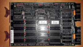
I need help to configure a DEC MRV11-C board for the usage with MXV11-A boot roms.

I have downloaded the 23-039D1 and 23-040D1 ROM images and looked at the first few entries of them:

15C0 = 012700
00E0 = 000340
8D00 = 106400
0005 = 000005

These four (4) words should appear at 773000 but seem to appear at 773010 (i.e. there either appears to be an offset applied or one of the address bits is 'wonky').

The other possibility is that the MXV11-A boot ROMs deliberately 'scramble' the address lines (both in the ROM programming and the board) and this causes the data to appear at the correct locations. The MRV11-C will not implement the same 'scrambling'. I don't know whether the MXV11-A actually does this 'trick', but I know other boot boards that do...

Perhaps check a few more words yourself?

Dave
 
@daver2: Thanks a lot for your analyses - maybe my attached files are a bit confusing, therefor I want to explain what I did:

240224_odt_read_universal_orig_at_773000.txt = boot ROM form a Universal Instruments 8222 machine controller, plugged and read at the original Universal Instruments board
240224_odt_read_universal_at_773000.txt = boot ROM form a Universal Instruments 8222 machine controller, plugged and read at the MRV11C board at chip set 1 position

The Universal Instruments 8222 original boot board does boot my PDP11 from an RX02 at 773010G. These ROMs do not work on the MRV11-C but at least the content is the same.

240224_odt_read_mxv11a_at_773000.txt = MXV11-A boot ROM, plugged and read at the MRV11C board at chip set 1 position
240224_odt_read_mxv11a_at_003000.txt = MXV11-A boot ROM, plugged and read at the MRV11C board at chip set 0 position

This ist in deed interesting and I will concentrate now on this, because the content ist different on the different chip set posotions and also probably damaged. I will now first read the EPROMs and compare the content with the original images.

The adventure continues ...

// Peter
 
I checked a further four words of the original ROM images, and I couldn't find this data at all in the ODT dump you did.

Yes, first thing is to check that your ROMs really contain the code you think they do...

Dave
 
Another thought (if you have some spare EPROMs).

For the high byte, initialise the EPROM programmer memory to 55h and then manually enter the data bytes 00h to 0Fh into the first 16 bytes. Burn the EPROM and install it into the high byte of the MRV11-C board.

Do the same for the low byte, but initialise to AAh and write the first 16 bytes as 0Fh to 00h.

This should give us word data values of:

000Fh
010Eh
020Dh
...
0E01h
0F00h
55AAh
...
55AAh

I leave it as an exercise to convert the word values from hex to octal...

Then use ODT to see what we get...

This should tell us:

1. If we have an EPROM in the wrong socket (the data value read for the associated byte should be 377(8)).

2. If we have the EPROMs swapped over.

3. If a data bit is stuck.

4. If we have some 'strange' behaviour.

The expectation is that the data words we installed into the start of each EPROM should appear at 773000(8) upwards.

Dave
 
I downloaded and compiled the tool ROMWak on one of my Debian boxes:
Code:
simh@innboxhd30:~/DECROMs/work/MXV11-A/roms $ romwak
ROMWak 0.4 - original version by Jeff Kurtz / ANSI C port by freem
usage: romwak <option> <infile> <outfile> [outfile2] [psize] [pbyte]
You must use one of these options:
 /b - Split file into two files, alternating bytes into separate files.
 /c - Concatenate two files : <infile1> <infile2> <outfile>
 /f - Flip low/high bytes of a file. (<outfile> optional.)
 /h - Split file in half (two files).
 /i - Generate rom information (size,crc) (as a text file).
 /m - Byte merge two files. (stores results in <outfile2>).
 /q - Byte merge four files. (See readme for syntax)
 /s - Swap top and bottom halves of a file. (<outfile2> optional.)
 /u - Byte update two files. (stores results in <outfile2>).
 /w - Split file into two files, alternating words into output files.
 /p - Pad file to [psize] in K with [pbyte] value (0-255).

NOTE: Omission of [outfile2] will result in the second file not being saved.

See the included README.md for more details. If README.md was not included,
please visit https://github.com/freem/romwak/
simh@innboxhd30:~/DECROMs/work/MXV11-A/roms $ romwak /m 23-039D1.bin 23-040D1.bin 23-000D1.rom
ROMWak 0.4 - original version by Jeff Kurtz / ANSI C port by freem
Merging bytes of '23-039D1.bin' and '23-040D1.bin', saving to '23-000D1.rom'
'23-000D1.rom' saved successfully!

I also see the expected content at 773000 now:

Code:
simh@innboxhd30:~/DECROMs/work/MXV11-A/roms $ od -w8 23-000D1.rom
0000000 012700 000340 106400 000005
0000010 111701 005004 012721 173032
0000020 010011 011706 011414 005724
.
.
.
0003760 105003 105737 176500 100375
0003770 153703 176502 000303 000207
0004000

btw. ROMWak has a very nice and structured source code ;-)

... continuing my research!

// Peter
 
One more thought:
The MXV11-A2 boot roms can be configured to either boot from a TU58 or to perform a disk boot (RX01, RX02, ...) This is selected on the MXV11-A board by a jumper (J29) which sets the address pin A09H either to high (1) for TU58 or to low (0) for disk boot. On the MRV11-C the the address pin A09H can not be configured. Maybe this is the reason (logic) why the code is shifted.

// Peter
 
My EPROMs look good, I read them in with a programer, dumped the content dan compared it with the original dump files - no difference!
You are probably right that at chipset 0 position one of the EPROMs might have been plugged not correctly - I will check this later but ...

The code which we see at 773000 results of the fact that the start address which I can select for the boot ROMs on the MRV11-C is either xx3000 or xx7000 depending on the chipset position. The MXV11-A boot ROMs are half empty, therefor at xx7000 is nothing. So I can only select xx3000 in order to select a memory position where something is. When you take a look at the "octal dump" in the attached text file, you find at 0003000 exactly the code which we see in my ODT dump.

Code:
.
0003000 010701 000402 005003 000423
0003010 012700 000340 106400 000005
.

@daver2: The question is now if this code is a valid boot code - here I need a little bit more help in disassembling and understanding the code, as well as to understand, how the MXV11-A boot roms are supposed to work on the MRV11-C board.

I attached one more document which I found about the MRV11-C board.

Thanks again for your help,

// Peter
 

Attachments

  • Applying_the_MRV11-C_board.pdf
    462 KB · Views: 1
  • 23-000D1_od.txt
    9 KB · Views: 1
Last edited:
One more interesting thing, at position 0001000 and 0003000 in the "octal dump" there is the same code.

// Peter
 
OK, there is a lot of things for me to read and digest there...

Lunch, washing up and a training course to do first though.

By loading the code into SIMH we should be able to disassemble it - or run the binary through a PDP-11 disassembled.

Dave
 
It looks to me as though the ROM image from 0 through 1777 is repeated in 2000 through 3777. This makes sense to me.

Just to confirm, do you now get exactly the correct image on the MRV11-C at the boot start address f 773000 upwards to 773777?

I agree that the MRV11-C board can't easily switch from one half of the bootstrap to the other, but we could bend an address pin out of each EPROM and pull it high. Not pretty, but it would suffice...

Just out of interest, if the bootstrap you are currently using for the TU58 works, couldn't we reassemble that for a base address of 173000 and burn that into a two EPROMs and just use them? Or is the pseudo dual boot facility a requirement?

If you have a BIN file now with the full bootstrap on it, you should be able to use SIMH to load the image into memory starting at 173000 and then use EXAMINE with symbolic display to disassemble it... I leave that as an exercise for you whilst I do my training course...

Dave
 
Yes, the second half of the EPROM appears to be the same as the first half.

It looks like the bootstraps do an awful lot more than a 'simple' bootstrap!

It also looks like the first bootstrap is a multi-device bootstrap - but it just keeps circulating around to find something to boot from (hence the apparent 'going to sleep'). None of the devices appear to be a TU58 bootstrap.

The serial (I am guessing) TU58 bootstrap appears to follow - requiring that one of the address lines of the EPROM is either jumpered HIGH, the appropriate pin of the EPROMs be bent out and pulled HIGH by a 1k resistor - or the second 'quarter' of the bootstrap be replicated four times within the EPROM or (as a minimum) copied to the first 256 WORDS.

In this case, I am just wondering whether it is not better to use a 'standard' (simple) TU58 bootstrap, suitably amended to include any hardware initialisation, and assembled for 173000.

Dave
 
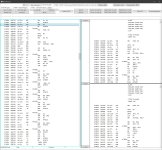
@Hunta: Thanks a lot for your disassemby and the coments ;-)
@daver2: What I really want is, to understand the MRV11-C in order to split at the end the MXV11-B boot ROMs into chunks to use them on the MRV11-C, similar to the BDV11 hack with the split KDF11-BJ ROMs. But this is future music because at the moment I am not even able to just plug the MXV11-A boot ROMs to my MRV11-C and just boot from an RX02 :-(

So for the moment my target is, to boot RT-11 on my PDP11/23 from an RX02 floppy with the help of the MXV11-A boot roms on an MRV11-C board. Because this is something that should work, as described in the manuals.

Many thanks again in advance for your help!

// Peter
 
So, you have an RX02 in the system and you are trying to boot from it using the MRV11-C and the boot ROMs that have been copied over?

You can see the 'correct' code (as per the first part of the octal dump you made) at 773000 to 773777?

Can you see the controller in the I/O page (with ODT)?

Can you document which cards are in the various slots of the backplane, identifying (in particular) empty slots.

Dave
 
Now I made a try with the MXV11-A boot roms at chipset position #7 and jumpered the boot multiplexer to 073000 as described in the manual.

20240303_190915.jpg

The result is the same, the CPU starts to read code and nothing happens :-(

@daver2: Yes I can see the RX02 controller and the system boots from it with the help of the Universal Instruments boot board.

I attached again the content which I read with ODT in this configuration in the file "240224_odt_read_mxv11a_at_pos#7.txt" and it appears to be the same which I have read previousely at 013000 at chipset position #1

@Hunta: Does the code which I read with ODT make any sense? It seems to be the code from my octal dump, beginning at position 003000 ...

Do you think that it will make sense to create EPROMS, where I shift the code with an offset to start at 003000? - But this can not be what was originally meant by Digital, what do you think?

// Peter
 

Attachments

  • 240224_odt_read_mxv11a_at_pos#7.txt
    3.8 KB · Views: 2
There are currently MRV11-C boards for a reasonable price at ebay ;-)
I am willing to invest in one more of these, to get this secret solved ...

// Peter
 
There should be no shifting of code etc.

What is in the beginning of the EPROM should appear at 773000 to 773777.

I see you have just posted a disassembly. I will have a look when I get home. Just out for an evening walk.

Dave
 
Back
Top