• Please review our updated Terms and Rules here

IBM 3278 Display - Analog Board Transformer Component

mtboody

Member
Joined
Mar 20, 2020
Messages
13
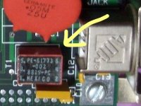
Hello - Is there anyone that knows the identify of the manufacturer or specifics of the component (highlighted in yellow) from a IBM 3278 Display units analog video board? From another unrelated board I saw on the internet, it appears to be a 6 contact transformer. I'm trying to get the part identified and replaced in order to get the display working. The tube and power supply is fine but the hv board is blowing a fuse on the low voltage board due to this faulty component. Unfortunatley it is located directly beneath a large heatsink which has been (so far) impossible to remove. So this is the best photo I have at the present time. Thanks for taking the time to read this post - any help is gratefully appreciated.

IBM 3278 Model 2 - Analog Board.jpg
 
Hello - Is there anyone that knows the identify of the manufacturer or specifics of the component (highlighted in yellow) from a IBM 3278 Display units analog video board? From another unrelated board I saw on the internet, it appears to be a 6 contact transformer. I'm trying to get the part identified and replaced in order to get the display working. The tube and power supply is fine but the hv board is blowing a fuse on the low voltage board due to this faulty component. Unfortunatley it is located directly beneath a large heatsink which has been (so far) impossible to remove. So this is the best photo I have at the present time. Thanks for taking the time to read this post - any help is gratefully appreciated.

View attachment 60393

Can you post the schematic that includes the area of this device.

If it is a small coupling or isolation transformer, it is fairly unlikely it would be the cause of fuse blows, regardless if it was open or had winding shorts. I could make a better remark on it if I could see the schematic.
 
Thank you for the reply - I do not have a schematic for the board. The board is meant to be swapped by a technician if the test procedure finds fault with the board as a whole. The board is markd "MFG LOC U" but nothing else to help find a schematic. A friend found that one of the high power transistors is shorted out (the pins are those exposed just above the transformer). It is one of those large silver button type transistors that is attached to the heatsink on the opposite side of the heatsink from which the photo was taken. I wish I had the expertise to remove the heatsink, but so far my desolder has not provided me with the ability to remove the heatsink from the board so I can have good access the transformer and transistor.
 
It appears to be a Pulse Engineering transistor (part # PE-61773-002). Unfortunately, no datasheet is available anywhere. It looks like only pins 1 and 6 are being used in the applications found so far. At least there is a bit more information to more forward now.

3278 pc board - zoom of front.jpg
 
It appears to be a Pulse Engineering transistor (part # PE-61773-002). Unfortunately, no datasheet is available anywhere. It looks like only pins 1 and 6 are being used in the applications found so far. At least there is a bit more information to more forward now.

View attachment 60479

Most likely the shorted transistor was responsible for the fuse blows.

If that is a small pulse coupling transformer, likely it will be ok and not responsible for any failure. These types of things are used to couple drive pulses into the base-emitter junctions of switching transistors. They can fail, its just that its pretty rare. The most likely failures on a board like the one in the photo would be the electrolytic caps, transistors, diodes & resistors and Tantalum caps in that very rough order. The large axial tant caps are usually fairly reliable.

Who was it that suggested the transformer was defective, what tests were performed on it ? (They can be awkward to test in circuit sometimes)

For a vintage item like this, the first step is to sit down with pencil & paper and patiently copy out the schematic. That way a structured plan of tests can be made to determine what is wrong.

The other approach is to test every component possible, the transistors and diodes with a meter, the caps with an ESR meter, for shorts and open circuit conditions and any resistors that are open circuit. Look for any parts that are thermally damaged. But this sort of approach won't always win and result in a successful repair, that is why its better to copy out the schematic and attempt to understand how the circuit is supposed to work and have a structure approach to the repair.

Having the schematic also means its possible to deduce the properties of some of the components, like transistors,which can be helpful if they don't have labels or have unusual numbers.

The worst move is shotgun replacements of parts.

It looks like a very high quality board to me.

It sounds like you need someone in your locality to repair it for you. The button shaped power transistors you refer to are T0-3 package types. Some can be NPN, others PNP and some could be Darlington types. In the latter case these can confuse people testing them because they can have internal resistors and a collector-emitter diode on the output device. So its also important to look up the specs of the part being tested (where possible) to correctly interpret the tests.

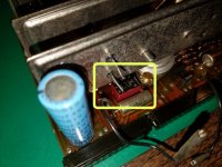
The second photo you posted shows a different, but similar part on the board in another locality on the same board ? Are there more than one of these transformers on the same board ? and if so why is the one under the heatsink suspect ? In any case if there are two of them, you can compare the properties of each to determine if one is faulty. I notice Pulse Electronics still exists. They appear to have made a lot of pulse coupling transformers.
 
Last edited:
It appears to be a Pulse Engineering transformer (part # PE-61773-002). Unfortunately, no datasheet is available anywhere

it is a 1:1 pulse transformer that IBM used in lots of places, most commonly as the output coupling transformer on 3270 coax interface cards

like Hugo said, it is very unlikely that it is bad
 
Also, It might be an unwise move to attempt to un-solder those heat-sinks. They probably have a lot of thermal inertia and it could risk pcb damage. If I was was repairing it I'd probably attempt to undo the screws from the thread side, by grinding two flats near the end,
to be able to grip and rotate it and possibly need to shorten the transistor pins a little, remove the transistor leaving, the heat sink alone. Then re-fit the replacement transistor possibly with the same screws or small diameter ones that clear the threaded hole with washers/nuts etc.

Actually, I cannot see in the photo, check if the screws securing the transistors to the heatsink have hex heads, the transistors may have been mounted with a small spanner after the heatsinks were soldered to the pcb anyway. In any case you could replace those with hex head screws of the same threads.
 
Last edited:
Thank you both for all the info! I was incorrect - Al is 100% - it is not a transistor but a transformer. The T1 on the photo from the one board I thought meant Transistor but it is is a transformer. I'm checking with Pulse but so far they seem to have reused the part #s but the new parts seem completely different. The board is an IBM 3278 HV Analog board. I am trying to repair the unit and have little experience. The board was looked at by an experienced tech and he pointed out that one or more power transistors were shorted and this transformer he was not aware of its functionality (he was experienced in CRTs but not this IBM unit). Using a 3278 Maintenance manual he was able to verify the power supplies work fine (all tested to proper voltages - 8vd, 12vdc, 44 vdc, etc at the test points). The top of the transformer appears to show damage/distortion from heat. Yes, indeed - I was able to remove one of the power transformers using a 1/4" open ended wrench. Luckily for me I was able to acquire two working 3278 terminals so this one may be used for parts and the shell will be reused with an LCD replacing the CRT and software used to provide the appearance of the 3278 terminal (Retro Terminal open source). It would be great to actually repair this board but I cannot locate anyone with the experience here in the Phila area for complete the task. All your advice is excellent - hopefully I can someday bring life back into this wonderful iconic terminal.
 
I was able to remove one of the power transformers using a 1/4" open ended wrench

? "Power transistors"

Well if you can test the power transistors and now you can remove them, it should be possible to find the defective ones and replace them. Most transistors can be tested with a simple meter. Look up testing transistors with a meter on the net and buy a meter.....the bottom line in most cases (not all, eg Darlington types and FETs) the three terminals appear as two diodes on the meter, so you are looking for that result, conduction in one direction not the other and the absence of reverse leakage and or shorts or open circuit conditions.

So if you could post the photos of the transistors with the markings/type numbers visible and the test results with the meter, we might be able to determine which ones are defective and what the replacement part should be.
 
If you are going to strip one for the shell, please take high resolution pictures of everything inside.
You might also want to check with the Living Computer Museum about restorations, they were working
on some in the past.

And hopefully yours came with keyboards. The keyboard ghouls love to butcher them and leave the CRT portion to rot.
 
Sorry for the typo - yup, I meant Power Transistors. I will do my best to gain access to the transistors for testing. Some are easier to access than others due to some be attached with screws to heatsinks and others being located under the heatsinks and directly soldered to the board. Those that are on heatsinks have wires that easily can be removed so the transistor can be tested in place. Hopefully I can get access to these parts for testing and identification marks. Thanks for your help!
 
Great advice. I will take hi res photos. And I do have a 3278 keyboard available. I am in the process of re-assembling from a thorough cleaning. It is a shame about the CRTs being cast aside. I now have 3 (two working and the one mentioned here that is having the issue with the HV board). It seems that now the 3278 CRTs are getting more difficult to find than the keyboards (especially those that are properly functioning). I was able to aquire the complete 3278 CRT and Keyboard in working shape and now am in the process of getting the shells powdercoated. Once the shells are returned and all reassembled, I need to get them working with my home Linux server. Slowly but surely I am making progress. But I really want to get the broken one working again as it is in good shape and just needs to get HV analog board's few components working. Backup plan is to use the shell and keep the internals for spare parts for the working units because the availability of parts for the CRTs will only be more difficult in the future. Thanks again for the great tech support here - it is most appreciated.
 
Its possible to test transistors in circuit too, the tests are less reliable, but sometimes they will identify a shorted or open junction. Not so good for testing leakage due to parallel resistances etc. So do all the tests in circuit first to identify any obvious suspects, rather than shotgun removal of parts. It is important to only unsolder/remove parts if there is good evidence of a failure, or without really good temperature controlled soldering irons and years of experience soldering & unsoldering, the pcb can get damaged and that is a real shame for vintage items.

So the basic tests are, meter set to diode mode (where it shows the forward drop of a diode) or meter on Rx1 resistance range: Check base to emitter in both directions, base to collector in both directions, emitter to collector in both directions. So that's six tests for each transistor to document in a table.

Also, when any transistors are removed, if there is any ambiguity, the current gain can be tested with a simple transistor tester, mostly the meter is enough. A really simple way to check power transistors is to wire them up with a 6V lantern battery and torch bulb and apply base-emitter current with a resistor to switch them on and light up the bulb. If you get stuck I can show you how that is done.
 
Last edited:
Sounds like good plan to test in circuit for obvious signs of failed components. I have a meter for testing and will follow the advice presented here. This website has been an absolute help in all respects for the excellent information from the user community. Thank you for all the wonderful support!
 
Back
Top