• Please review our updated Terms and Rules here

IBM 5100 - worklog

mt777

Experienced Member
Joined
Apr 28, 2019
Messages
141
Location
Poland, USA DE
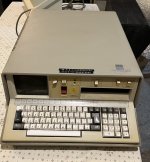
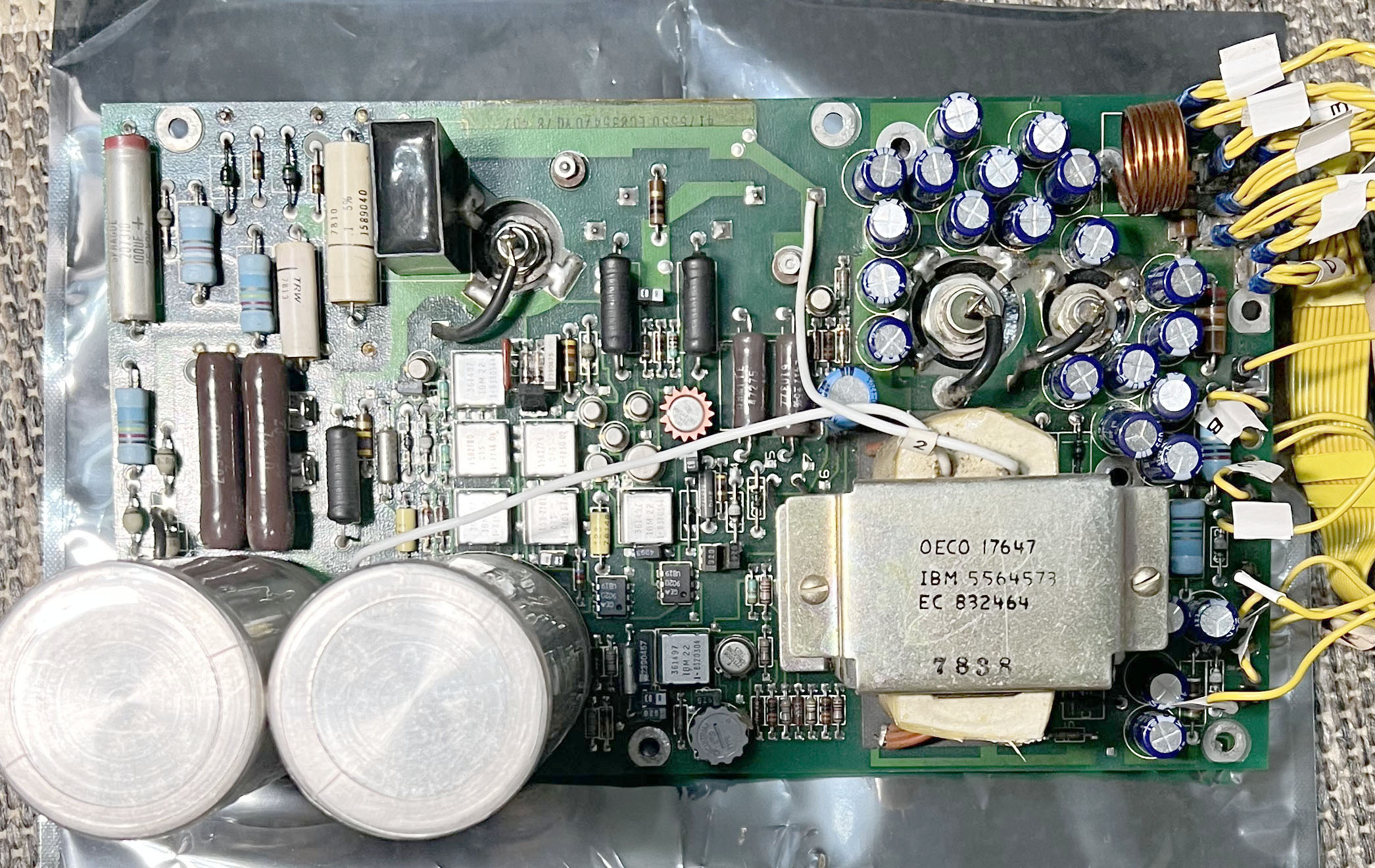
Recently purchased the unit. It was tested by seller but in my home fuses were blown during connecting to power (on OFF state). Got advices to check capacitors in AC Box (it may be also false positive alarm).

Will try slowly go thru each step to clean it and restore. During this worklog advices are welcome as I am not so familiar with pre-XT stuff.

1. DISASSEMBLY

Not so much for the first day. Disconnecting CRT was easier than expected. 3 screws and edge connector cable. Didn't have next to me 9mm wrench so removing AC box will be in next step.
 

Attachments

  • 5100.JPG
    5100.JPG
    3.4 MB · Views: 15
The ac filter is what you have shown, and is easily tested with a meter.
High resistance across the line and load ends.

Also check the power supply RIFA caps. To find it, follow the cables attached to the load end of the filter.
 
Been over twenty years ago but recall having to replace one of the high voltage DC filter capacitors in the power supply. They have a first-generation switching supply and the filter capacitors in the primary side tended to short.

Easy to check by opening up the power supply and checking the two biggest capacitors in it to see if one is shorted. Remember that is a Hot chassis switching supply so unless you know what you are doing don’t mess with it with it connected to the AC power!

Hard to imagine today but at one time back in the eighties had two of those systems, one was Basic only and the other was Basic and APL, also had a printer along with tons of programing tapes including the IBM Basic course.
 
Currently on inspection is AC Box, as house fuses were activated on OFF machine state.

I tried open case of PSU too in meantime but top 4 screws is not enough. Seems that plate is also screwed in back side with port connectors and don't know now how to disassembly it.
 
If you have the system plugged into a GFI protected circuit it may trip due to leakage of the AC Input filter. The threshold of the GFI circuits is way sensitive and will trip on the smallest amount of AC leakage to ground. A lot of those old AC Line filters were way too leaky when new but back in the day before modern GFI stuff that was not an issue. Check your DC resistance between both sides of the AC plug to the ground pin. there should not be a reading. also with the main AC switch turned off you should have no reading between any of the three pins. There are ground interrupt adapters that effectively remove the ground pin from the circuit and some people have used them to get around the GFI issues, myself just make it a point not to have any GFI devices protecting the workbench outlet circuit.
Modern AC filters generally don't have this issue but remember back when they built that system dinosaurs still roamed the earth, the 5100 has a modern design although not PC style high frequency switching power supply, they built it to be difficult to get into because of the dangers involved in that style of Hot AC input switching supply. That system was introduced before the first generation IBM PC and has a lot of the old series propriety IBM square chips and edge connectors so in some ways its a lot like working on a old IBM series 360 mainframe. Originally when opening the hinged cover they had a awful foam block that pushed down on all the cards on the mother board and that dam thing deteriorated and that crap ran all over the cards and everything else in the case, this was what i remember from way back in the eightieths so cannot imaging how bad a untouched unit would be today. from the looks of it some fortunately removed that years ago.
From the picture it looks like the Basic system, so when you get it working it will do a quick post and show you the amount of memory and be ready to go in IBM Basic. you only need the tape cartridges for storing or loading programs. although you can do fun things like look at the registers there is no other operating system under Basic.
 
Finally I opened AC Box and now I understand why it was so annoying... I put new photos of it to AC Box link.
 
Knife + Hammer on the straight sides. At corners I had to use screwdriver + hammer.
Don't know what's next.
If well understood @Qbus then nowadays AC Box is not so important and can skip melting this black shit and just do a bridge?
But from my personal curiosity I would like to see whats the real content and issue...
 
Pin to pin on AC input side 0.3 Ohms! man that thing is toast. Yes, you can just jump around it. that was intended to prevent the HF Radio noise of the power supply from getting back out on the AC Line along with preventing other noise on the house side of the line getting into the power supply. Think you can find them on eBay all day long just has to be close, same current rating or more, fit in the same location. I have been doing this stuff for a while now and never went thru the trouble of opening one of them myself because of the potting and all that.
If you bypass it check the resistance to ground on both AC Lines going into the power supply, shod see nothing to the frame (electrical) ground on both legs and preferably not a dead short across the input with the AC switch turned on.
Important, do all this with the AC disconnected from the system first! On that system the ground lug connects to the frame in the system. after bypassed and before plugging in confirm ground pin to frame connection and that there is no connection between the two AC pins and ground.
If you are not familiar with working around lethal voltages get someone to help you.
 
yes, obviously unit was disconnected all of the time. I think that will be around 1 month from last power on by seller (where worked..?).
Could you provide example of replacement of this ACbox?

Also I think how to open PSU shell without disasembling everything? To check if there are RIFA caps and do visual inspection at least.

I don't like indeed hi-volt mechanics but some times ago I recapped IBM 5154 so with following advices I believe that we can do it safely.
 
Here are my notes related to the power supply on the 5110 (which is the same between the 5100 and 5120 -- on the 5120, it has two power supplies, one for the disk drive, then the 5100/5110 equivalent power supply is buried deeper inside the belly of the system, but is exactly the same dimensions and build as the prior models).


Can't speak to that AC box, other than to say I was able to by-pass it entirely with a modern day laptop power brick (19V). As long as you're using the system inside in temperature controlled room, the fan isn't critical. So if you just want to see/verify if the rest of the system works, you could do that temporarily. Or if you get really stuck, I do have a spare original power supply that still works.

Absolutely label those yellow cable ends before disconnecting any, or else it becomes some real spaghetti tracing them again later.

I'm not sure if the rear video BNC works with the main CRT disconnect - never tried that. But if that main CRT isn't working, I do know that white cable going to the rear BNC does still get signal (when the main CRT and its PCB are connected to that blue 8 or 9 pin connector)- so it's a way to use the system even if the main 5" CRT has died.

Hope your tape unit in that system also works! Good luck
 
Last edited:
On the bottom of the system I think were 3 flush mount screws. They hold in the rear external IO piece, but the PSU cover might be screwed to that IO piece also.
 
3. PSU rotated

I have removed shield from PSU. It was easier than thought (2 mounting screws needs to remove and then psu body can be rotated to vertical position).

Now must try pull the psu board to replace these 1000uf capacitors. Not sure if there are RIFA caps too...
What about this big 450VDC cap?
 
Back
Top