• Please review our updated Terms and Rules here

IBM 5140 PC Convertible Recap and More

pcuser451

Member
Joined
Aug 19, 2023
Messages
16
Hi,
New user here, I am just posting to ask questions, gather information and to leave some documentation to assist future collectors

I recently came into acquisition of an IBM 5140 PC Convertible, and there was three areas of, interest here. (Images will be included)

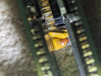
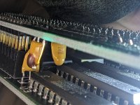
1. Power Board Recap. My machine does turn on an function as normal, however due to next issue, I decided to check the power board. The caps look fine, but looks can be deceiving. So I do want to replace them, I made some preliminary notes on capacitor location and values, but some of them are hidden, and I do not want to desolder them just yet.(Fig 1,2,3) so I am asking the members of the forum here: have any of you experience recapping this particular machine? If so, did any note down their values? Let me know
2. LCD Hum, My machine is an later model with backlighting. A few days into operation. I encountered an issue where the backlight did not function, and its slider did nothing. I knew that the panel was removable, so I did that, and reseated the edge connector, and the backlight worked again, but this time with a noticeable hum/ whine. I did some research, and most info pointed to backplane/ inverter issue. I want to know if this is an indication of the panel failing, or just age, and if there is any solution to this? Thanks
3. Final point is that my machine's battery door compartment is missing, and I want a 3D printed cover, and I couldn't find anything about that.

Any fellow members can let me know, I know this a very long post for a new poster like me, I just wanted to cover my bases. Thanks

My Basic Documentation

Figure 1:
PXL_20230819_140515327.jpg

Figure 2:
PXL_20230819_140455185.jpg
Figure 3:
PXL_20230819_140533525.jpg
 
Looks can be deceiving with electrolytic caps. Even if they don't have dome tops.

The main think though is to not replace parts on hunches they are bad, or because somebody else says that all electrolytic caps should be replaced. Always replace parts on the basis of diagnostic testing, especially if all looks well with them and there are no physical clues.

A better plan is:

Inspect them physically, any sign at all of physical leakage of electrolyte (or gas pressure with a dome top) replace them.

If they appear physically normal, test them. Firstly with an ESR meter in circuit. If that test is ok, likely the cap is too.

There are cases where the ESR can still be reasonably low and the caps uF value has dropped. If there is any concern in that area, disconnect one lead, often it can be freed up in the pcb hole with a solder sucker, then test the caps uF value on a capacitance meter.

In fact it turns out that a lot of vintage electrolytics were simply better made than some modern ones (though you can't go wrong if you stick with high temperature rated Nichicons or Panasonic parts) You will find that modern parts are always physically smaller for the same uF value and voltage rating compared to vintage ones.

A capacitor, being a physical object that dissipates some heat (on account of its ESR in pulse circuits or its leakage resistance in DC circuits), always runs cooler when it is physically larger part for the same ESR value. Heat is the nemesis of the electrolytic cap, either generated within it or proximity to hot objects such as heat sinks.

In many designs you will see heat sinks wrapped around an area where the electrolyics are and in some cases cuddling them tighter than their true love. This significantly shortens their life.
 
Last edited:
Alright, thanks for the advice, I"ll look into that, and definitely invest into an ESR meter. As for my other two inquests, I guess as long as the LCD panel works, the inverter hum is just an annoyance, and the only way to solve that is with another panel. which is rare to come by.Though I am still intrested in a solution for the battery compartment door, as I was wondering if anyone who owns an IBM 5140 still has theirs and could make an STL file of the battery door? If so, that would be helpful. I don't know if this counts as requesting a service, but I think it relates to this computer, in a practical way. Lemme know though. Thanks
 
Since reading the LCD connector got it working again, I wonder if a little deoxit might help clear up the hum. It's possible that it's getting enough connection to display, but not enough to work 100% properly. Otherwise I would suspect a problem with the backlight inverter, if it has CFLs. Inverters use high voltages and as they start to fail, it's not uncommon to get a hum or buzz that is the same frequency as the power coming in.

I did have a power supply that buzzed and turned out to be a large filter capacitor that had dried out. The AC power was arcing to the inside of the can, making a low pitch but very loud buzzing sound.

Good luck with the repair! It's a neat little machine.
 
I'm of zero help to you with hardware, but I am the former owner of one of these machines. So my advice to you is to find a program that will let you run EGA programs on the Convertible.

I think it was called something like SimEGA. I used it to play SimCity on my Convertible, even though the Convertible only had CGA graphics. It also greatly expanded the library of software available for that machine.
 
Update: So in the intermediate time between this, I ordered a nos IBM PC Convertible CRT Display Adapter to test its cga abilities via composite out. However, when I attached my crt adapter in, and turned on the computer, the computer refused to load from floppy drive 1. I took off the adapter, checked the power board, looked fine, tested the computer again, at which point it functioned like before. The adapter emitted a horrible smell, at which point I opened it to check, and unfortunately, two of the tantalum capacitors had decided to give out. I was thinking of replacing them, however, doing some light research, it seems these capacitors are very special, and hard to source. I've attached pictures, one to show the damaged cap, and one to show the values on a good cap.
 

Attachments

  • 20230917.jpg
    20230917.jpg
    1.9 MB · Views: 6
  • 20230917 (2).jpg
    20230917 (2).jpg
    2 MB · Views: 6
If I'm reading it right, the first line is the capacitance. You take the first two digits and then multiply them by 10 to the power of the third digit, which gives you its capacitance in picofarads. So 10 x 10⁶ = 10,000,000pf. Which is 10uf.

The second line is the maximum voltage The capacitor can handle and a tolerance code. So this is a 16v capacitor with a 10%± tolerance. I don't think you should have any problems finding a 10uf 16v tantalum capacitor. Somebody check my math though. I always have to look this stuff up lol
 
Back
Top