• Please review our updated Terms and Rules here

IBM 5151 display - toasty inductor

tom.storey

Experienced Member
Joined
Nov 18, 2022
Messages
107
Location
London, UK
Hi all,

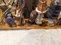
While dismantling my 5151 for cleaning today I noticed that there is an inductor which looks like it has been quite toasty at some stage. Maybe its still working(ish) because the monitor itself does work and displays an image (although there is an ever so slight "wobble" from time to time), but it looks like a bit unhappy and it could probably do with replacing.

Does anyone know what kind of part I should look at replacing it with (value, etc)? The component designator is L502, and its along the top side of the board with all of the adjustment pots.

Everything else is looking fine so far (visually), but if there are any other things I should look at doing I'd appreciate some pointers.

Thanks!
 

Attachments

  • PXL_20221129_143331372.jpg
    PXL_20221129_143331372.jpg
    2.5 MB · Views: 25
  • PXL_20221129_143356071.jpg
    PXL_20221129_143356071.jpg
    2.6 MB · Views: 25
I didnt even think to look for a service manual or anything - didnt think they existed!

I'll take a look at that. Thanks!
 
Its first Gen IBM, its really well documented. I got that from the SAM computerfacts repair manual for the 5151.

also remember its a Greater than notation so you dont need to find the EXAXT match, it can be a greater value. I just spent 2 minutes looking.
 
If it was my monitor i would unsolder the inductor and clean the leads.
Its not common for that type of inductor to fail. The solder joints ... yeah fail a lot.

joe
 
One of the solder connections is obviously bad, and has been heating up due to high contact resistance. Remove it, clean up the board, and scrape any oxidation off the wires, then reinstall it. That will probably take care of your shaky picture too.
 
Interesting observation. If the inductor had actually failed I guess the monitor wouldn't be working at all, or at least not displaying a picture correctly because it seems to be connected to the horizontal deflection coil of the tube.

I'll give this a try.

All other solder joints are looking good so far.

The only other observation is that it looks like the diodes for the bridge rectifier on the AC input must get a bit warm because the PCB is discoloured around them.
 
The only other observation is that it looks like the diodes for the bridge rectifier on the AC input must get a bit warm because the PCB is discoloured around them.
Thats not uncommon with monitors, slight scorching from diodes. I would investigate the inductor solder joint before worrying about that.
 
It is probably not an ordinary inductor.

It is a Ferrite bobbin which has had a permanent magnet attached to the top of it, for the purpose of correcting the usual errors in H scan linearity that result from reversal of the deflection yoke's magnetic field after flyback. It is a very long story.

But what it means is that this inductor, unlike any common others you will meet, is polarity sensitive. If you remove it an accidentally install it in the reverse direction, the H scan linearity in you VDU will be messed up.

The reason it overheated was that the solder connection to it was poor and became resistive generating heat. The peak current in this part of the circuit, at the beginning and end of H scan is in the order of 3A. So it evolved heat. This cooked up and carbonized the normally light brown looking contact adhesive that was applied at its base.

So remove the inductor, clean up the mess, and make sure to re-fit it with the correct orientation, which, luckily won't be difficult because you have taken a photo.

I don't own a 5151, and I'm not sure where the inductor L504 is located on the pcb or what that one looks like, which might be another LIN inductor.

The way to tell if your inductor is a lin inductor, is to place a small screwdriver near the top of the coil, if it is a lin coil there will be a permanent magnet field there.
 

Attachments

  • Lin5.jpg
    Lin5.jpg
    108.4 KB · Views: 6
You are right, the top is magnetic.

I did notice that there was a dot on the PCB, and also a corresponding mark on the component itself, and I made sure to reinstall it as per original orientation.

(Analogue is far from my comfort zone.)

The PCB trace is quite fragile now, having removed the component and disturbed it, so I've reinforced the connection with a couple of runs of wire (wrapped around the component leg as best I could so it hopefully wont become detached). Hopefully that will be enough to keep it happy for a while.
 
The PCB trace is quite fragile now, having removed the component and disturbed it, so I've reinforced the connection with a couple of runs of wire (wrapped around the component leg as best I could so it hopefully wont become detached). Hopefully that will be enough to keep it happy for a while.
If you get into that situation a good method to repair the pcb and make a solid mounting for the component is to use miniature eyelets, there are some remarks on how to do it here:

 
Back
Top