• Please review our updated Terms and Rules here

IBM 5151 Monitor

stangman517

Experienced Member
Joined
Dec 15, 2014
Messages
243
Location
Georgia, USA
Greetings all.
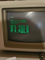
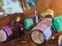
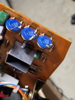
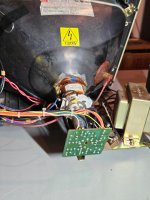
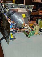
I recently installed a cap kit to this unit and that went well. I probably didn't need to do this, but I did even if I found out why it wasn't displaying text. I was testing it in a dead 5150 board using SuperSoft and nothing displayed, so I assumed the monitor hence the cap kit replacement. Found if the 5151 isn't receiving signal it won't display anything. What I need some help with is this. When I use a working 5150 mobo and it displays text the first few lines are nice and clear and normal 80/25 size. However as the text keeps scrolling each lines keeps getting smaller and smaller to where you have to glue your face to the monitor. I tried adjusting pots but nothing helped. Any ideas? Running MS-DOS 5.0. Thanks
 
When I use a working 5150 mobo and it displays text the first few lines are nice and clear and normal 80/25 size. However as the text keeps scrolling each lines keeps getting smaller and smaller to where you have to glue your face to the monitor. I tried adjusting pots but nothing helped. Any ideas?
A vertical linearity problem by the sounds of it. Post a photo.

The vertical deflection circuitry in the IBM 5151 is shown at [here]. Note the voltage warning.

Is the +15V DC okay, or is it something significantly lower?

Notice the vertical linearity adjustment, VR403 ('VERT LINEARITY'). Was that included in your adjustments?

Nearby are capacitors C403 and C404. Did you perhaps use incorrect replacements ?
 
M7 here are my results. C403 and C404 I did not change; I only changed the electrolytic caps I got from console5dotcom. Yes I did adjust VR403 with no change.
If I understand correctly you needed the voltage checked on diode D403. If this is correct the voltage is 0.715. Both the anode and cathode sides of D403 have black marks with the cathode side the worse.
Pin 2 on TDA1170 is 14.51V, pin 5 is 13.95V. All values collected while monitor is connected to the 5150.
Included a pic of D403 - not the best pic.
 

Attachments

  • Diode D403 burnt.jpg
    Diode D403 burnt.jpg
    137.8 KB · Views: 20
Here's the pic while I look over the schematic you sent me.
This is indeed a vertical linearity problem.

If I understand correctly you needed the voltage checked on diode D403.
It's a generic diagram intended for a wide audience. The comments do reflect the fact that checking supply voltages is standard practice.

Pin 2 on TDA1170 is 14.51V, pin 5 is 13.95V. All values collected while monitor is connected to the 5150.
So supply voltage (and through to the chip) to the vertical deflection circuitry is good. That ruled out.

Included a pic of D403 - not the best pic.
I just see a little black coating on the pins. That is nothing that would worry me.

C403 and C404 I did not change; I only changed the electrolytic caps I got from console5dotcom.
- Worth while removing those from circuit (lifting one leg is enough), and then measuring them.
- A check of VR403 is worthwhile.
- Of course, the TDA1170 is a possible suspect.
- It seems unlikely that the fixed value resistors have gone bad.
- A bad solder joint is a possibility.
 
Ohms for VR pots from L to R: VR401: 13 ohms - 80K, VR402: 172K - 220 ohms, VR403: 185ohms - 82K.
I tripple checked solder joints entire board: Good
Haven't had a chance to lift a leg and test C403 & C404: will tomorrow.
 
VR403: 185ohms - 82K.
82K ohms ?

Something is wrong there. Both IBM's circuit diagram and SAM's circuit diagram indicate that VR403 is 50K ohms. That means that, measured in-circuit or not, 50K is the most you should ever read between any of VR403's three legs.

You will find procedures online on how to test a potentiometer.
 
I checked again:
Important: the VR401, VR402, VR403 on my board has only two legs. Pic attached.
VR401 from turning the dial Left to Right: 137 ohms to 80K ohms (the above number I left off the 7),
VR402 from turning the dial Left to Right: 171K ohms to 222 ohms,
VR403 from turning the dial Left to Right: 177 ohms - 82K ohms.
I see what I'm seeing, and I had the meter set to Ohms (omega symbol).

C403: 155nF
C404: 158nF
 

Attachments

  • VR Pots.jpg
    VR Pots.jpg
    102.7 KB · Views: 10
since the vertical linearity pot VR403 has no effect, check R405 in-circuit, should be about 56K. What is the voltages at pins 1 and 10 of IC401 ?

Larry G
 
A few pics of the tube/yoke. There's what appears to be two different hot melt glue colors. Why two different colors? Does this possibly indicate someone adjusted the yoke at some point?
 

Attachments

  • Tube Pic3.jpg
    Tube Pic3.jpg
    179.1 KB · Views: 14
  • Tube Pic6.jpg
    Tube Pic6.jpg
    136.5 KB · Views: 14
  • Tube Pic8.jpg
    Tube Pic8.jpg
    143 KB · Views: 14
It's not a yoke problem. 14V on pin 1 is very wrong, supposed to be 3.1V. What is the voltage on pin 10 = 2.3V.
If it's close, check R406, if ok then IC401 is probably shorted pulling pin 1 up to the pin 2 power rail. If pin 10 is high,
check R407, R408 otherwise still could be bad IC401 as long as C405 replacement is correct value/polarity.

PS - the glue at the top of the yoke at the bell of the tube doesn't look original to me. And always check circuit trace
paths while checking components. It's easy to lift a solder pad while replacing parts. I've done it myself many times over the decades of repair business.
 
Last edited:
The raster scan is exhibiting a fairly classing vertical non linearity defect which is as good as an oscilloscope recording of it.

As the scan advances, the rate of change of current with time is falling away, that is why the scan lines become progressively closer together (this assumes though the yoke is normal see point 7)

This is highly characteristic of the drive amplifier (includes items to be discussed below) not being able to provide a sawtooth current.

If you look closely at the oscillogram though, of the output voltage of the IC pin 4, during scan time, you will see that it falls at a slightly higher rate than linear, this helps maintain the linearity toward the bottom of the scan. This is achieved with + feedback from the output to the sawtooth generator part of the IC via the linearity correcting components.


Assuming the Yoke is ok, and one of its two Vertical coils not O/C, then this is characteristic of resistance in the power delivery system that should not be there.

The possibilities are:

1) The output coupling capacitor, C408 (2200uF) has gone high ESR (but you may have replaced that already).

2)The power supply feeding the Vertical osc and output IC is sagging down as the current load increases toward the end of V scan,. To check this you need to put a scope on the IC's power pin 2 to check for a downward voltage tilt over the course of the V scan, possibly because C409 has gone high ESR.

3) One of the output transistors in the lower leg of the complimentary output stage inside the IC is failing and has become resistive and unable to adequately sink current.

4) All of the above are normal and the drive waveshape to the power amplifier section of the IC is abnormal. You can check the waves there with the scope.

5) An out of spec component in the Linearity control circuit.

6) Other anomalies like a high resistance joint in series with the yoke, or.....

7) (Heaven forbid) one of the two vertical yoke coils is open circuit creating a non-linear deflection field. Since they are in parallel, you would have to know what the usual DC resistance of the yoke would be to test them. Without that information the two coils can usually be disconnected at the tags on the yoke for testing.

With regard to lifting solder pads:

Generally these VDU's have single sided non-plated through hole boards. So if you apply fresh solder (which adds some flux) to the pad and component lead you want to un-solder, then press solder wick over that, with your soldering iron, it forces the pad toward the pcb surface and it wot't lift. The solder is easy to clear away with wick, or a sucker, on single sided boards. Pad lift happens when there is a combination of heat, and force from the component lead before the solder has fully melted and this pushes the pad off the pcb surface. So never melt the solder while manipulating the lead & component at the same time, or you can push pads off the pcb surface. (the rules are a little different for plated through holes boards)
 
Last edited:
I could have mentioned that the CRT's beam is deflected perpendicularly to the applied field from the Yoke's coils, so the H deflection coils are the ones on the bottom and top that flare a little onto the tube bulb (where that glue has been applied- I would try not to disturb that for now). The V coils are the ones wrapped around the dark grey Ferrite shells. Look very carefully at the wiring leading from the V coils to the tags where the 180 Ohm damping resistor R413 is mounted.

(this is one of the many exciting things about the three dimensional nature of the mag deflected CRT, the beam is deflected at right angles to the magnetic field and also both those are at right angles to the beam current)
 
Last edited:
Retrogear I provided wrong values for pin 1. I measured them without C403 and C404 soldered. When I put them back pin 1 = 8.6V. Pin 2 = 14.4V, pin 10 = 2.1V.
C405 was replaced with a 50V 10uF instead of 16V 10uF.
Had only 1 pad lifted and I scraped a small area on the traces and flowed solder to it from the pin.
R406 = 21.7K, R407 = 1.75K, R408 = 1.1ohm.
If I need to verify any value please let me know.
 
5) An out of spec component in the Linearity control circuit.
Hugo I wouldn't know about this. I've had it since 2015 and just recently broke it out to discover these symptoms. What happened prior will remain a mystery. The different colors of glue made me think someone has tinkered with the yoke at some point; likely an experience tech. You and the other guys are extremely informative, and much is new information to me. Some of your info makes me think "huh?" I have to digest it some; then it's better. ;-)
Oscilloscopes I have no experience except for toy ones I built from kits, but not a real one.
The cap replacement kit I got from console5. A fella named Luke is very helpful. Kit: ==> https://console5.com/store/ibm-5151-monitor-cap-kit.html/
Let me know if you want me to check anything else.
 
turn up your brightness to make the background raster visible. If you turn up the vert height can you get the raster to fill the screen ? If it fills the screen, now does the
vert linearity stretch out the bottom half ? The reason I'm asking is the height and linearity adjustments interact with each other so one setting can affect the other.
 
Last edited:
Did the failure you currently have appear before you re-capped the unit and it was unchanged by re-capping it, or did it occur after the re-capping ?

Also why did you re-cap it ? did ESR tests on the capacitors show them to be defective and /or they were out of spec on a capacitance meter ?
 
Hugo the failure was there before the re-cap. I re-capped only because of these symptoms. I don't have a ESR meter, but ordered one.
 
turn up your brightness to make the background raster visible. If you turn up the vert height can you get the raster to fill the screen ? If it fills the screen, now does the
vert linearity stretch out the bottom half ?
Yes the raster does fill the screen and it does stretch out to the bottom except to about 1" from the bottom of the screen.
 
Back
Top