Chuck(G)
25k Member
Okay, go back and check the voltages. When you get things back, pay attention to page 23 "Miscellaneous Adjustments".
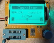
Refer to an 'ESR chart'. Search the internet for those. A 'bad' cap is expected to have an ESR that is very much larger than the chart-indicated ESR value, e.g. chart indicates 0.012 ohms and I measure 0.7 ohms.I guess a good one should show just under one ohm ESR, right ?
Thank you for your input, Andy!
I do have an ESR meter. Did you also have a 'black screen' monitor or what was the fault in your unit?
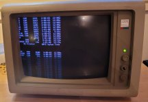
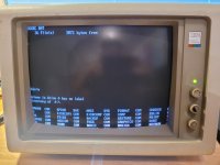
Picture did not come back just by tweaking RT1 on the power supply. I still have good(ish at least) power values
from the power supply, so I think I will next open up the video box and the video board and see what is going on in there.
Looking at the PSU schematic, the 7.4V (3) derives from the 56V line. So if you've still got 56V on 4, then check R114 (180K). If that checks out, then the suspicion is T120 (BC237B) has gone shorted. We can discount small signal diodes D121 and D501, whose purpose is to make sure that the 7.4V doesn't rise above the 10V feeding the 5V regulator (7805).
So, the procedure is to check to see that you have 5.0V from the sub-regulator board and that you also have 56V on terminal 4, but nothing on terminal 3 (7.4V)
") . I also notice improvement in the image,
. I also notice improvement in the image,